What's new
Van's Air Force

Don't miss anything! Register now for full access to the definitive RV support community.

Another Garmin G3X Touch Canbus question

QuixoteAg

Well Known Member
Patron
So i'm working on the design of my avionics/electrical system and am planning on routing the canbus cable as follows on my RV6 build:

G5 (pilot side)(terminator)
GDU 450 (pilot side)
GTR 200 (center of panel)
GMC 507 (center of panel)
GEA 24 (shelf behind panel)
GAD 27 (shelf behind panel)
GSU 25 (shelf behind panel)
GSA 28 Roll Servo (under seats)
GSA 28 Pitch Servo (bell crank behind baggage bulkhead)
GMU 11 Right or Left Wingtip

I get that the entire canbus run needs to be 66' or under

Also in the install manual it says to keep "stub nodes" under 12" - ok, that makes sense until i get to the first A/P servo which obviously will be > 12" from the GSU25 behind the panel....and then it needs to go several more feet to the 2nd A/P servo and then to the end of a wingtip.

I figure I'm not the first person to run into this but it just confuses the heck out of me how you would keep the nodes under 12" when they are at the end of the wingtip....or is the whole "under 12"" think just for the stuff behind the panel?

Thanks!

It all makes sense to me until i get to the first GSA28

Stub nodes are like "T"s in the trunk line. I prefer no stub nodes and would much rather daisy chain LRU's that are between the two nodes at the ends of the trunk line where the terminators must be.

There may be cases where you have to run an "out and back" with the trunk line to a distant LRU to prevent a stub or "T" in the line.
The trick is to optimize the routing to minimize the "out and back" distance. Should be easy with an RV-6.

They are not telling you that you can't have more than 12" between LRU's.......
 
Last edited:
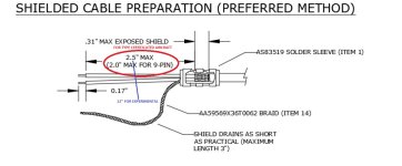
The devils in the terminology used. By stub node Garmin means the distance from the CAN Bus splice point where the shielded harness wire splits out with a Y to connect to the two DSUB pins that insert into the LRU. You are lucky you have an experimental because the STC'd version documentation reduces this distance to 2.5". So it's not the distance between LRUs as you are describing. It's just the local node stub out from where you put the shield drain on the Y to the component.

See attached picture showing the stub length call out from the STC'd installation manual. I don't know why Garmin has tighter length of 2.5" for type certificated aircraft but allows 12" for experimental aircraft. Point is just try to make these as short as possible for good data reliability.

FYI: The 60 foot maximum CAN Bus length is the value for using standard MIL M27500 shielded wire for the CAN Bus. If you use the more expensive CAN 120 Ohm specific wire the maximum length increases to 100 feet.
 

Attachments

  • StubNode.jpg
    StubNode.jpg
    100.8 KB · Views: 92
Last edited:
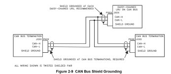
See figure 2-6 and 2-9 from the AU installation manual. Note how the CAN Hi and Lo wires essentially "loop to/through" their respective pins on each LRU connector. This is the "stub" length that they are concerned about.

Keep it to the minimum workable distance in order to crimp and secure a D-sub pin on a wire and then connect that wire to the respective CAN Bus wire (about an 1" or so).
 

Attachments

  • Screenshot 2023-09-28 at 1.31.16 PM.png
    Screenshot 2023-09-28 at 1.31.16 PM.png
    226 KB · Views: 78
  • Screenshot 2023-09-28 at 1.30.51 PM.png
    Screenshot 2023-09-28 at 1.30.51 PM.png
    321.7 KB · Views: 84
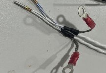
Sometimes a picture is worth a thousand words. Here is one way of avoiding the stub if you are using 24 gauge wire.

You also need another termination. I suggest the GMU11 which will keep the can bus shorter.
I would also term at the pitch servo instead of the G5 which will keep the can bus shorter.

By terminating at the end of your longest runs the can bus is shorter since there are no return lines.
 

Attachments

  • IMG_1186.jpg
    IMG_1186.jpg
    182.2 KB · Views: 74
Last edited:
Back
Top