What's new
Van's Air Force

Don't miss anything! Register now for full access to the definitive RV support community.

Adding Manifold Pressure

Pounder

Well Known Member
Sponsor
With the CS prop conversion, this ship needs to monitor MP.

As remedial as this should be, is there a suggested plumbing set-up?

Current Engine monitor is EIS 4000

Probably tapping into a cylinder head, with hose or hard tube to fire wall.. I think?

And send to the the GRT sensor for EIS 4000.

A picture would be worth a lot of thumb taps..


Thanks everyone..

Bryan
 
TS Flightlines

With the CS prop conversion, this ship needs to monitor MP.

As remedial as this should be, is there a suggested plumbing set-up?

Current Engine monitor is EIS 4000

Probably tapping into a cylinder head, with hose or hard tube to fire wall.. I think?

And send to the the GRT sensor for EIS 4000.

A picture would be worth a lot of thumb taps..


Thanks everyone..

Bryan

TS Flightlines has a nice fitting and hoses.
Fitting has a restrictor. It fits the port on #3 cylinder. Since you don't have P-mags, the line would go to your MP Transducer. If you add P-Mags later, it's a simple change in plumbing. Tom can supply the hoses and fittings.
 
Exactly as Wirejock says.

If you can find an unused fuel primer nozzle you can use that as a starting point, or go the TS Flightlines route. The fitting needs a restrictor though. I have a VA-168 Manifold attached to my firewall and the MAP, Oil Press and Fuel Press all terminate there with the sensors in the manifold and the wiring going back to the EIS4000. I used a solid primer hose between the engine and the manifold which left over from the engine build as I have fuel injection and didn't need the primer lines.

Place a nice hoop in the solid line to take up movement between the engine and the firewall.

If you zoom in a bit you can see the VA-168 Manifold on the firewall in behind the engine mount. The beauty of using this is it gives you room for changes in the future. I have a spare tapping point for the MAP which I will use in the near future to enable the variable timing on the Surefly SIM's.

There are many ways to skin the same cat but hope that helps.
 

Attachments

  • 20220623_162912_resized.jpg
    20220623_162912_resized.jpg
    298.5 KB · Views: 74
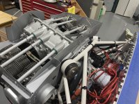
These pics may be hard to visualize, but basically I came off from the #3 cylinder primer port via a restrictor fitting and a flex line from TS Flightlines to an AN fitting attached to my motor mount, and from there to a #4 aluminum hard line to a firewall bulkhead T, feeding the GRT manifold sensor - aft of the firewall, and also my manifold sense line to my SureFly ignition for ignition advance - not yet attached in this photo.

IMG_2301.jpg

IMG_2235.jpg

The first pic shows the steel braided flex line from the engine to the fitting attached to the engine mount. The second pic shows the hard line going from the flex line fitting to the AN “T” bulkhead fitting (blue) on the firewall. The aft of the fitting that goes through the firewall has a barbed fitting inserted in it (modified) to which I attached a 1/8” ID flexible silicon hose that goes to the GRT manifold sense module. The other side of the firewall mounted bulkhead “T” on the forward side of the firewall, not attached yet in this pic, goes to my vacuum advance for my variable SureFly ignition sysatem.
 
Last edited:
Rubber hose from engine to MAP sensor.

For instance RV-14 puts an AN840 hose nipple into the #3 primer port and runs a rubber hose to the MAP sensor.

GRT shows a "vacuum hose" at the sensor. RV-14 shows a "fuel hose" from nipple to Dynon MAP sensor with constant-tension hose clamps at each end.
 
Back
Top