What's new
Van's Air Force

Don't miss anything! Register now for full access to the definitive RV support community.

adding an oil separator...

Thanks Allan for posting some answers.
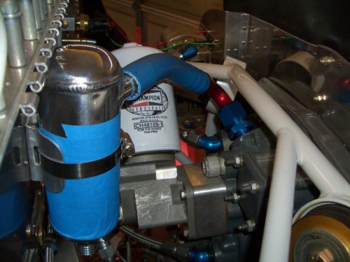
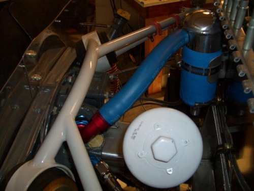
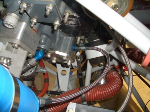
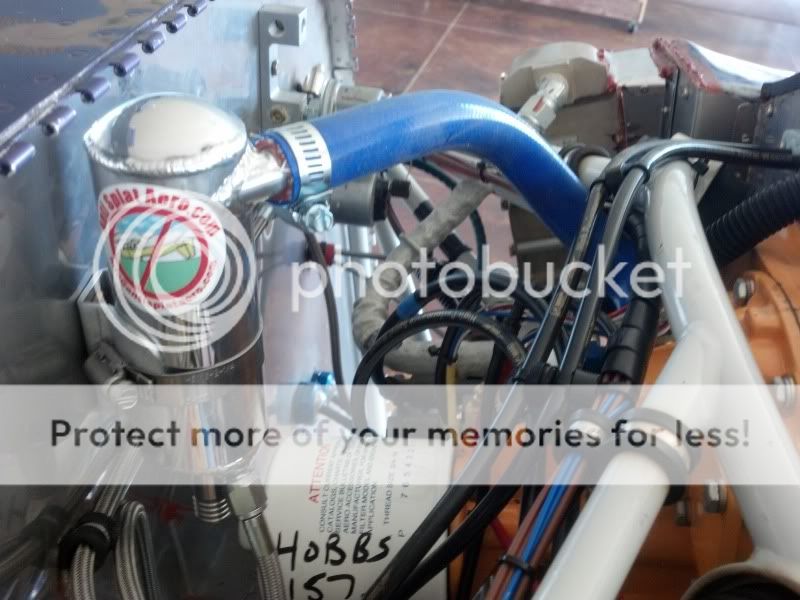
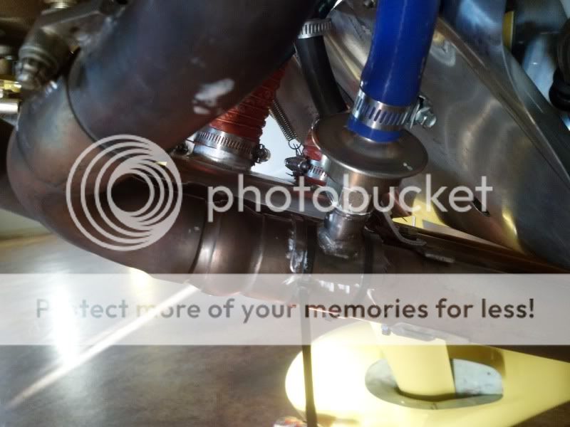
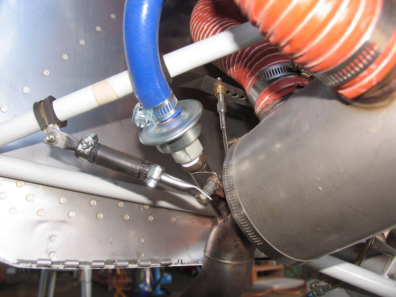
Looking at my installation pictures I may be just around 45 degrees and "puddling" was what I was hoping for.
By puddling I understand collecting the one or two drops of oil that make their way down the tube and end up on the hangar floor after shut down. I thought that the reed valve would capture these after shut down and burn them off again when the exhaust system is hot. Having put a few hours on before installing the reed valve I can say there was no oil getting on the floor as opposed to the standard installation without the oil separator.
Maybe you can explain what you mean by puddling and why I would not want that.

IMG_2765.JPG


IMG_2757.JPG
 
Last edited:
Just an observation here...that brace you have on there to the engine mount will most likely cause more harm than good....The engine mount is stationary, that exhaust is tied to the motor which will move around a bunch! The brace is going to put some high stress on that tube.
 
Exhaust brace

No, not really. That is a standard brace for all of the Vetterman exhaust systems. The rubber hose allows for support without a "hard" connect that would cause the stresses you mention. Look at my pictures a few posts earlier.

Vic
 
....In theory that is correct, but if you do as we do and install a temporary gauge on the crankcase you will see that this is not the case. The pressure fluctuates considerably when the engine is running. If you crank your engine over with the starter (mags off) and place your hand over the breather you will feel the engine suck and blow on your hand as described.

I'm sure a fast response sensor on an ordinary open breather will record pressure oscillation pretty close to a sine wave, for at least two reasons, maybe more. However, it will be all or mostly an oscillating positive pressure, with little or no negative component when running....blow-by is always adding to the crankcase gasses.

Your previous statement was "The major portion of the pressure reduction is accomplished via the pumping action of the crankcase as it volume changes throughout the rotation of the engine. The valve allows air to exit but not enter, thus creating a pressure drop.

Crankcase volume does not change. There is no driver for a negative case pressure merely by placing a reed valve in the breather line, as there would be with a single or opposed twin. Here the negative pressure source is external.

It's easy to prove or disprove, in the field, with an old mechanical gauge or with a transducer. Tap the breather line for pressure measurement. Record breather pressure with the reed valve connected to the exhaust pipe. As previously measured and posted here, the average will be negative. Now remove the reed from the exhaust tap and cap the tap fitting. Leave the reed connected to the breather hose, with the end formerly connected to the exhaust open to the atmosphere. Make another identical run. If your assertion is correct the mean pressure will be only slightly less negative. I say it will be positive. Care to wager a ten spot presented on bended knee at the next RV beer social?
 
No, not really. That is a standard brace for all of the Vetterman exhaust systems. The rubber hose allows for support without a "hard" connect that would cause the stresses you mention. Look at my pictures a few posts earlier.

Vic

While the 10 looks different, my Vetterman braces hook to the engine. Looks like the 10 uses some sort of flex cable to minimize the stresses.

The brace in question is "inline" more or less with the rotational axis of the engine. I still say that ain't a good idea but hey you guys are the experts....

This is a little off topic for this thread, but I called and spoke with Larry Vetterman about this exact issue when hooking up the supports for the 4 pipe exhaust on my RV-7. He said that some of his systems are designed to be supported from the engine and some from the engine mount and was adamant that I follow his recommendation to support my system from the engine mount.
 
This is a little off topic for this thread, but I called and spoke with Larry Vetterman about this exact issue when hooking up the supports for the 4 pipe exhaust on my RV-7. He said that some of his systems are designed to be supported from the engine and some from the engine mount and was adamant that I follow his recommendation to support my system from the engine mount.

Not talking about Larry's intended purpose for what he provides. He obviously knows what's best.

I am talking about how this mount is being used to "brace" that stub that has been welded to the exhaust.

Anyway, my opinion is worthless in this matter so back to the regular scheduled program...;)
 
Brantel,
The brace you are talking about was part of the installation before the stub was added. As you can see from the brown mark on the white engine mount it was merely moved over a bit to provide space for the reed.
Like Vic pointed out, it's a flexible connection where the stainless tubes on each side of the flexible hose are used only for attach points and serve as
an anti rotation brace that can be adjusted to different lengths.
The main support is the flexible steel cable attached to a flexible support from the top down.
The entire muffler installation moves around about a half inch in all directions
and is installed as per Vetterman instructions, hope that helps.:)
Back to harnessing crank case vacuum.
 
I'm with Brian concerning the mount.

The mount itself does a good job of supporting stuff and still flexing. But by attaching the support between the engine mount and the reed valve tube, you are transferring all the load from the exhaust and heat muff to the tube weld.

Could be wrong. Give us a report in 100hrs.
 
I don't have a picture from the other side but there is a ring clamp around the exhaust pipe hidden from view.
You can see the rusty little stub coming out from the right, that is the attachment flange. The stub is attached to it with yet another somewhat flexible stainless clamp to accomodate heat expansion.
 
Oil Consumption Update

For those that have installed this, could you post an update on how it has affected your oil consumption?

thanks,
 
I couldn't find the information on the anti-splat website. What are the inlet and outlet fitting sizes? I'm guessing 3/4" in and 5/8" out?
 
For those that have installed this, could you post an update on how it has affected your oil consumption?

thanks,

I think you will find little reduction in consumption. An amazingly small amount of oil makes and amazingly big mess. I installed one to keep oil off my prop. (Yeah, it's behind the engine where it belongs:), I saw very little difference on my ~75hr engine, and I average about 10 hrs/qt. so I deduce that most of that is burned instead of blown overboard since Allan's separator seems to work probably close to 100%, at least on my install.
Good product....happy camper.
Tim
Cozy MK IV
Dues paid
 
performance testing underway...

Check valve installed... evaluating performance impact ;)

img3314ap.jpg


The photo is a bit deceiving in presenting the relative angles of things... the entry pipe is angled back 5-10 degrees and canted off center about 15 degrees pointing directly up to the separator and giving a bit better clearance... and the immersion point is back cut about 45 degrees giving a flow presentation of 35-40 degrees (ish)
 
Last edited:
The other day I received a few parts that I ordered recently. Included in that was the anti-splat air/oil separator, plus some fittings and hose from Earl's performance. I came up with a solution to replace the breather hose supplied by Vans and the problem of routing the hose around the 90* oil filter adapter. I didn't want to use a 90* fitting that came on my engine. Not that there is anything wrong with the fitting, but to remove or install the fitting, the engine has to be removed from the mount (a big PITA).

From Earl's perfomance I ordered and aeroquip -12NPT to 3/4" barb 90* (full-flow) push-on hose fitting. I also ordered a 1/2" NPT to -12AN straight adapter. Earl's also sells hose for push-on fittings in large sizes so that is compatable with engine oil and combustion gasses.

I mounted the air/oil separator to the firewall backed up with a doubler to spread the load. I installed the adapter fitting in the engine and then connected the separator to the engine with 3/4" hose and the aeroquip fitting. I still need to fine-tune the clock position of the separator and trim the hose a bit (can't forget to add the clamps). I think this solution will work out pretty good. The fittings weren't all that expensive, less than $25 for both and the hose was $6 a foot, took about 8-9inches.

I ended up using a straight fitting at the oil return rather than a 90* to keep the hose clear of the battery box. If I change the clock position of the separator I might be able to change fittings.


FP26022013A0001V.jpg


FP26022013A0001W.jpg


FP26022013A0001X.jpg
 
Last edited:
Anxious to see your results

Stephen - Please don't forget to get back to us with your results - considering adding an oil separator too. Thanks!
 
Last edited:
Oil use down

Although 11hrs/qt was a healthy oil consumption on a new engine I added my oil separator reed valve some 22 hours ago at 130 hours of engine operation.
While indications on the dip stick are less than accurate they nevertheless point to a significant reduction in oil use.
From what I can see, I am down just a little over half a quart in the 22 hours since oil change.
If I had to quantify oil on the belly, I would say, zero, zip , nada. dry and clean.
I usually measure the oil quantity that I drain at oil change to be perfectly sure what went in and what came out and how much was burned or blown out.
It's too early for that but I wanted to give a quick update on my findings.
 
Sun-n-Fun number 3...

This was the third year making the trek from Seattle to Sun-n-Fun and back.
The first time was with regular mags, second with a single P-Mag.
This year: two P-Mags, the oil-air separator, and the vacuum check valve.

For all phases of flight out and back; this year just over 6,000 miles.

Oil consumption was less than 1 quart in 15 hours (down from 1 in 8-10)

Cruise speed up 4 mph and with a slight increase in fuel burn, up .1 GPH
 
Tube weld cracked out...

As an ongoing follow up on my experiences... The vacuum check valve tube into the exhaust weld totally cracked out. It is now welded back in place with a couple of side braces and a trailing gusset. Hopefully it will eliminate the moment arm vibration and last. Pretty sure that some additional bracing is required and should be addressed during the initial install.
 
just started my oil separator install last night. I was looking at the location for a check valve. I'm planning on a clamping arrangement, so I can avoid welding directly to the exhaust pipe.
 
OUR MISTAKE!!!!!!

As an ongoing follow up on my experiences... The vacuum check valve tube into the exhaust weld totally cracked out. It is now welded back in place with a couple of side braces and a trailing gusset. Hopefully it will eliminate the moment arm vibration and last. Pretty sure that some additional bracing is required and should be addressed during the initial install.

...I am sorry to hear you had a problem with the cracking. I feel like this is my fault as I didn't properly explain the installation of this fitting. When I look at the photos you put up, I see you installed the fitting and tube full length. I left these tubes long to make for more versatility in installs of aircraft other than RVs. The tube only needs be 1&1/2" in length when installed. This reduces the vibration by a very substantial amount and will eliminate the cracking. The valve at that distance will not be affected by heat from the exhaust and will most likely outlast your airplane. I will send you another tube and fitting (no charge) and some stainless gussets if you would like, just let us know. This offer holds true for anyone with this issue, or anyone that wishes to eliminate the potential. Again I apologize for this and would like to make it right. Thanks, Allan...:eek::eek::eek:
 
I'd love some stainless gussets - I'm maybe a week or two away from installing mine. If you've got some stainless sheet scrap cut up into gussets I'd sure be interested...
 
shorter pipe and bracing...

...I am sorry to hear you had a problem with the cracking. I feel like this is my fault as I didn't properly explain the installation of this fitting. When I look at the photos you put up, I see you installed the fitting and tube full length. I left these tubes long to make for more versatility in installs of aircraft other than RVs. The tube only needs be 1&1/2" in length when installed. This reduces the vibration by a very substantial amount and will eliminate the cracking. The valve at that distance will not be affected by heat from the exhaust and will most likely outlast your airplane. I will send you another tube and fitting (no charge) and some stainless gussets if you would like, just let us know. This offer holds true for anyone with this issue, or anyone that wishes to eliminate the potential. Again I apologize for this and would like to make it right. Thanks, Allan...:eek::eek::eek:

Thanks Allen, a reduced length would help the moment quite a bit and reduce the potential for cracking... still, it might be best to add a gusset and a side brace. This length guidance is good, what are the temperature limits for the check valve? I sure don't want to have a failure from excessive heat.

We made a 'monster garage' fix and welded in side braces and a rear gusset after welding the pipe back in place... not ideal since we did not have any stainless scrap on hand and ended up using some 4130 steel. If it fails it will likely fail the whole exhaust pipe where it has been thoroughly abused ;) I might end up having another end section of exhaust made up and cut the check valve out and start again. I am pretty sure that I can salvage the part though.

I think that a strap based solution, similar to some smoke system injectors, might be preferable...
 
Allan, what do you think of hydroguy's idea of using hose clamps, similar to the way we install EGT temperature probes. It sounds like a good idea, as it would only require a hole and no welding.

If this is an okay idea, would it be possible to offer a tube with a contoured plate on one end, which we could clamp to the exhaust with 2 hose clamps or so.
 
Got my oil separator mounted today using the Stephen Christopher "extra hand" method.......still need to install the check valve.
IMG_20130505_170720_110_zps79cab282.jpg


The 90* fitting supplied hits the engine mount, so I used a 45* fitting instead. It's the smaller fitting in this pic with the braided hose on it.
IMG_20130505_164012_365_zps6ba19243.jpg
 
Last edited:
I can't believe the difference! I called Anti Splat Aero, described my set up to them and three days later I have the complete kit. I installed it on Saturday and flew 2.5 hours on Sunday. Went from blowing a quart every 5 hours to zero lost in 2.5. I had everything I needed in the kit including the gussets. I cut the valve down to 1.25" as stated in the directions so I don't expect any problems with the weld cracking.
What a nice kit and great customer service.
 
Thanks Allen, a reduced length would help the moment quite a bit and reduce the potential for cracking... still, it might be best to add a gusset and a side brace. This length guidance is good, what are the temperature limits for the check valve? I sure don't want to have a failure from excessive heat.

We made a 'monster garage' fix and welded in side braces and a rear gusset after welding the pipe back in place... not ideal since we did not have any stainless scrap on hand and ended up using some 4130 steel. If it fails it will likely fail the whole exhaust pipe where it has been thoroughly abused ;) I might end up having another end section of exhaust made up and cut the check valve out and start again. I am pretty sure that I can salvage the part though.

I think that a strap based solution, similar to some smoke system injectors, might be preferable...

... The temperature the valve can handle is very high and with 1.5" of straight tube it will last forever. They were designed to handle being attached directly to a cast iron exhaust manifold. I think you are correct about the half pipe clamped on type of arrangement being more trouble free and simpler to do for most people. I will try to make some up and put them on our web-site. Then all that would be required is to drill a hole and clamp it on. Thanks, Allan ...:D
 
... The temperature the valve can handle is very high and with 1.5" of straight tube it will last forever. They were designed to handle being attached directly to a cast iron exhaust manifold. I think you are correct about the half pipe clamped on type of arrangement being more trouble free and simpler to do for most people. I will try to make some up and put them on our web-site. Then all that would be required is to drill a hole and clamp it on. Thanks, Allan ...:D

Do you have a clamp type ready to ship? I was going to build mine tomorrow after work....but I could hold off if you are ready. My welding skills need tuned up before I get it built I'm sure.
 
Do you have a clamp type ready to ship? I was going to build mine tomorrow after work....but I could hold off if you are ready. My welding skills need tuned up before I get it built I'm sure.

No, I don't have them just yet, but it looks like I should get after it by the number of e-mails and interest. We are in the middle of building a run of 200 RV-8 Ultimate Gust Locks right now. As soon as we get to a point where we can through these in we will make some. Thanks, Allan...:D
 
It's ok Allen. I was just yanking your chain. You have some good products and have been open to changes, good job.
 
Allan, I like the idea of a dedicated port into the exhaust, in fact I have been considering doing that for a smoke system too. I haven't pursued it in enough detail to determine what I would need to do to install one though. It looks to me like I would need to remove the exhaust pipe tails (last foot or so up to the swivel joint in the pipes) so I could have them on the bench to weld on the ports. Not knowing how hard that would be, it seems like a hitch in the plan, and i'm not keen to try welding while they're still on the plane... My fuel lines are pretty close!

Being able to just twist the pipe in that last swivel joint, drill a hole, clamp on a port, and twist it back into place seems much more do-able, and makes the process more attractive. Something to consider, maybe?
 
... The temperature the valve can handle is very high and with 1.5" of straight tube it will last forever. They were designed to handle being attached directly to a cast iron exhaust manifold.

Right offhand I don't recall any application attached directly to the exhaust manifold. Can you suggest one?

A typical installation located the check valve on an air rail, which was in turn connected to the manifold...random illustration grabbed off the net below.

3151qu9.gif
 
Got my fitting installed last night....well almost. I forgot the clamps.

IMG_20130510_194443_688_zps830e09c5.jpg


This morning we were faced with a 2.5 hr drive to Missoula to watch the grand daughter play lacrosse. Instead, I installed clamps and cowled up. We were there in 40 minutes even had headwinds. Gut impression says I am faster. I've flown enough to know that 8.5gph gets me 177-178 KTAS between 9-11000'. Today I noticed we were holding 180 for most of the trip. I realize this wasn't a real test run but did make me take notice. I fiddled with the mixture to see make sure I was where I normally ran. Coming home it was too rough over the mountains for any useful data collection. I had the power pulled back. 5.8gph=150KTAS but still wacked around, so down to 130 and 4.? gph.

Life is good
 
saddle

Brian, That looks very nice.The blue high temp silicone hose that I used fit very tight so I skipped that hose clamp.(less wt. shaking) I am at 8.8 hrs. with no oil on the belly and saddle assembly looks perfect. More hours will tell but so far so good. Ron
 
Got my fitting installed last night....well almost. I forgot the clamps.

IMG_20130510_194443_688_zps830e09c5.jpg


This morning we were faced with a 2.5 hr drive to Missoula to watch the grand daughter play lacrosse. Instead, I installed clamps and cowled up. We were there in 40 minutes even had headwinds. Gut impression says I am faster. I've flown enough to know that 8.5gph gets me 177-178 KTAS between 9-11000'. Today I noticed we were holding 180 for most of the trip. I realize this wasn't a real test run but did make me take notice. I fiddled with the mixture to see make sure I was where I normally ran. Coming home it was too rough over the mountains for any useful data collection. I had the power pulled back. 5.8gph=150KTAS but still wacked around, so down to 130 and 4.? gph.

Life is good
...This looks very nice and for sure will be trouble free forever. I think I need to pre-make some of this type of mountings for the guys that don't have ready access to welding equipment. It will vastly simplify the install and totally eliminate the possibility of cracking Etc. Now all I need do is find a source for those ultra high temperature zip ties and we will be good to go.:rolleyes: Thanks, Allan
 
...Now all I need do is find a source for those ultra high temperature zip ties and we will be good to go.:rolleyes: Thanks, Allan

:D. I figure the zip ties will melt and glue everything in place....I replaced them with SS clamps that I had left in my other truck. Amazing they seem more secure.

Allen, I was going to wait for your product, but I had the plane apart and ability to roll my own. I flew 2 hrs today and ran at a higher oil level than in the past...so far so good.
 
...This looks very nice and for sure will be trouble free forever. I think I need to pre-make some of this type of mountings for the guys that don't have ready access to welding equipment. It will vastly simplify the install and totally eliminate the possibility of cracking Etc. Now all I need do is find a source for those ultra high temperature zip ties and we will be good to go.:rolleyes: Thanks, Allan

sign me up for one of your systems as soon as you've got the clamp on saddle arrangement done.
 
I got my vacuum valve with clamps (thank you Allan), and i assumed it would be an easy install. Murphy strikes again!

Unfortunately, it turns out there is precious little straight runs in the exhaust system on the -10. I am still unsure of exactly where i can mount it appropriately.

It looks like most -10 welded installs put it right on the curvy part of the tubing, which won't clamp well with the clamp system.

There is a chance it will fit on the only straight section right underneath the firewall but the clearances are tight. Also, it will make removing the hinge pin difficult.

Argh!
,
....If you can take some photos and tell us what you need we will make you a custom part to solve the problem. very sorry to hear you ran into this. Allan...:confused:
 
Hi Allan... it's certainly not your fault! you delivered exactly as promised. i was so excited about not having to farm out for the welding job, that i hadn't even considered any other possibility other than this would be a cinch. ;)

I'd be more than happy to take some photos, but it may take a few days. I did find this link below to Ernst's post that shows the -10 exhaust. You can see how it curves straight out of the heat muff.

http://www.vansairforce.com/community/showpost.php?p=744618&postcount=51

It might be possible to fit the clamp right in Ernst's same location with a smaller clamping plate, possibly.

I didnt have much time to study it today. Unfortunately, it might take me a few days to get time to look at it again.

I hope someone else may have a suggestion as well. Thanks again for all the help and great products!

Jae
 
Jae,

you may consider a location up near the header, there are straight sections
on both sides.
According to Dan Horton, this area of the exhaust is more efficient but
it is almost uphill from the exit of the separator.
There is simply no straight section downstream from the mufflers that can accept a saddle fitting.
 
I didn't find much room upstream the muff either. The pipe runs are fairly tight there, too.

I finally got around to it and got it mounted. I ended up mounting it to the side where the clamping plate fit without modification. I thought i would need to trim some of it but never did.

No test flight yet, since I have to wait for Obama to leave tomorrow!

20130606_175716.jpg


20130606_175643.jpg
 
Nice job

That looks nice and seems to fit perfectly.
Mine is welded in place right there and works great.

Sorry you are locked in by the Presidential TFR,
great timing for Golden West.:(
 
I have a question. While I love the idea of removing air pressure from the case, what happens when the valve stops working? If it fails open, no problem....but if it fails closed...wouldn't it blow out a seal on the engine? Couldn't that get rather interesting in flight if it blows oil all over the place?

Are we expecting a moving part with baked oil on it to never stick?

.....I addressed this it another thread and you need not be concerned. The valve is a reed valve and the only kind of failure it can have is wide open if the reed were to break the only consequence would be a loss of the gained performance improvement. We have been using and selling these systems from 1969 to date (many thousands) and I can't remember ever seeing a failure or a bad valve. Hope this puts your mind at ease. Thanks, Allan...:D
 
Last edited:
Back
Top