

Hartstoc
Well Known Member
[Otis, I edited the text format to eliminate the huge font in your original version; S.Buchanan]
Necessity really is the mother of invention. I've been pondering the challenge of retro- fitting fuel return lines to RVs and other aircraft for over two years. Those for my RV-7A need to be installed without removal of wings or tanks, and no access to the tank interior is possible without violating the difficult-to-access and heavily pro-sealed mid-cord sending unit flange . I’ll be posting a separate thread titled “Reasons you might need fuel return lines” soon.
I thought through several possible designs and I even prototyped a couple, but none were particularly satisfying. Then, about six months ago, Inspiration led to a design so elegant, easy, and reliable that It deserved protection, so I engaged an attorney and obtained US Provisional Patent #62/900,809. This new fitting can be used to add a fluid or gas line anywhere on any thin-walled tank with limited wall curvature, even where zero access to the tank interior is possible.
Right now I’m putting out feelers for a*production and marketing partner with CNC milling capabilities in order to offer this to the aircraft market (and the auto racing after-market?). Ironically, developing this idea has set back work on my own RV mods by about three months, but I hope that, in the end, others will benefit.
At this moment, working prototypes are at the anodizer(two for installation in my 7A and two as demo units), and I’ll soon be working on an installation video that I plan to share on VAF. Below are some preliminary photos. Note that these make use of some unfinished parts, so you will see some roughness in ring grooves and surface finish. A damaging fire at one of my properties has brought a pause to normal life, but I wanted to get the word out on this hopefully “coming soon” retrofit option. Before long I will update with more info, imagery of fully finished parts, and an installation video.
Features:
1- It is quick and easy. It can be installed in an RV in about one hour per side working within the space available between the wing and fuselage. The circular stiffener pressed into the forward root rib near the leading edge provides an ideal installation location.
2- Installation requires ZERO access to the tank interior, except through a small opening made entirely by working from outside the tank. The product kit will include an installation template that will be secured in place with aluminum tape to enable precise, easy cutting of this opening using a tiny carbide burr on a Dremel tool, and will include hole-locators for the two 3/32” retaining cap-screws. I’ve developed an installation strategy that keeps the tank interior absolutely clean during installation that will also be covered in the video.
3- The assembly includes rigid inner and outer flanges that sandwich the tank wall very firmly, preventing any significant strain upon it once installed.
4- It does not require the use of Pro Seal or any other type of sealants, relying instead upon Viton O-rings embedded in each face of the outer flange. It can be placed in service immediately.
5- It is permanent, yet can be easily removed for inspection and servicing in less than one minute if desired. (Plus one safety wire if desired but this is not required as it is intrinsically self-locking).
6- It promises extreme reliability and airworthiness.
7- *It is cosmetically beautiful, with no connectors other than the AN flair fitting visible from outside the tank(more a factor for high-wings with visible tank ends than for RVs).
8- Many, including me, might actually install it in new builds as well as retrofits and for feed lines as well as return lines, especially in aircraft with visible tank ends. Using one for feed-lines would provide for the very easy servicing of a finger screen on the pickup line inside the tank. Photos follow here:
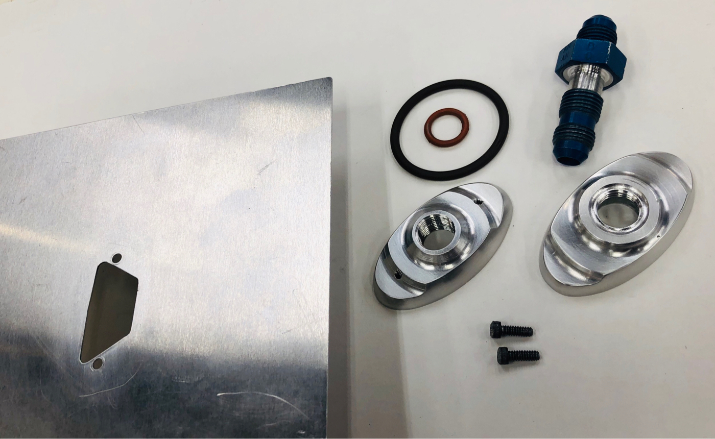
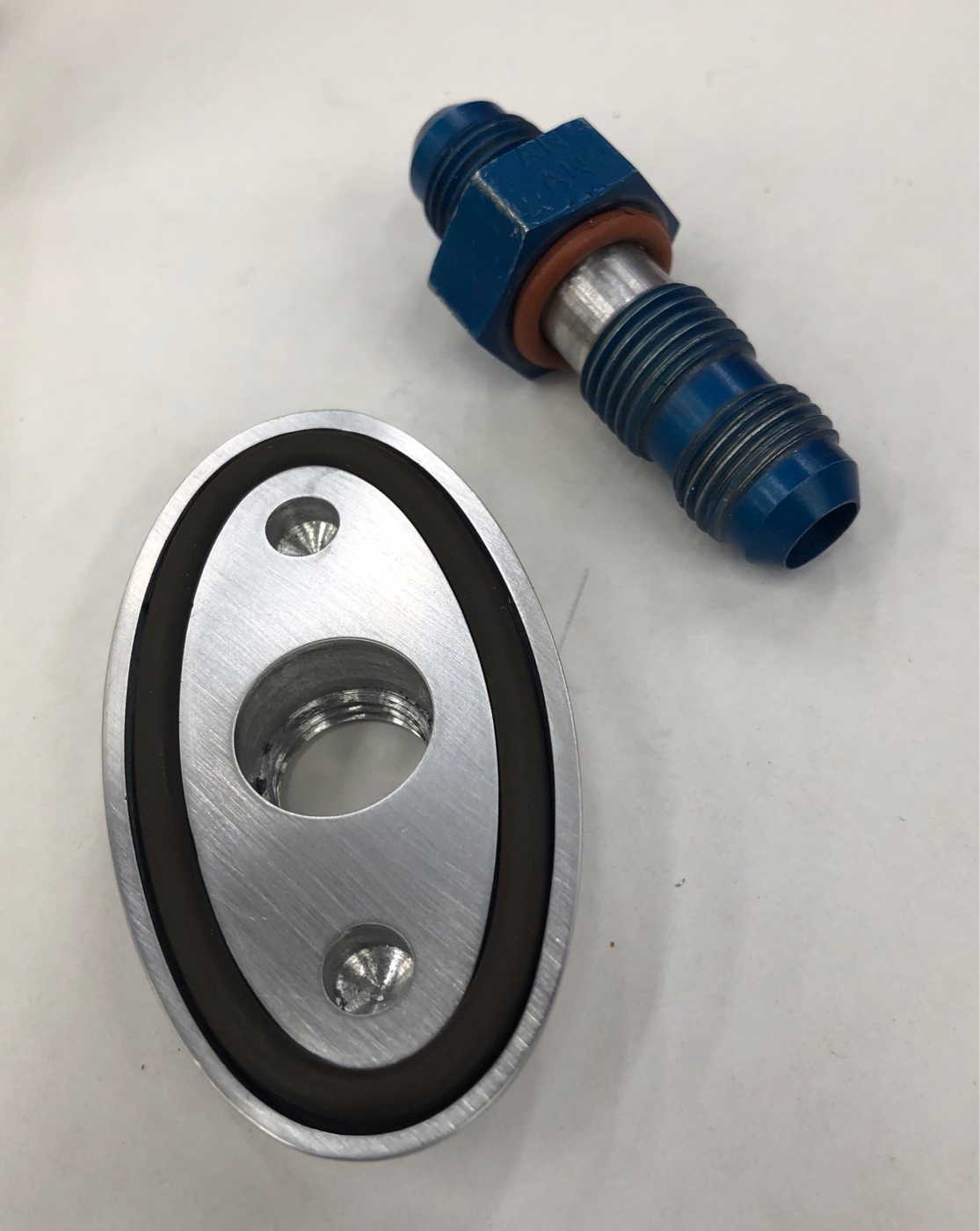
This shows all of the parts, including a tank cutout mock-up. The working name is the “0tis elipt0flange” tm, patent pending #62/900,809:
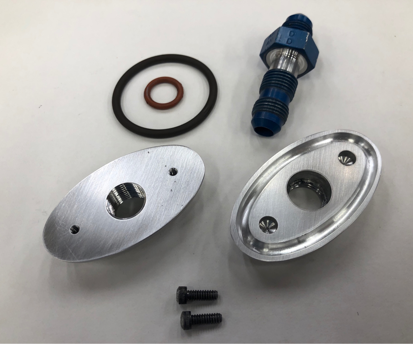
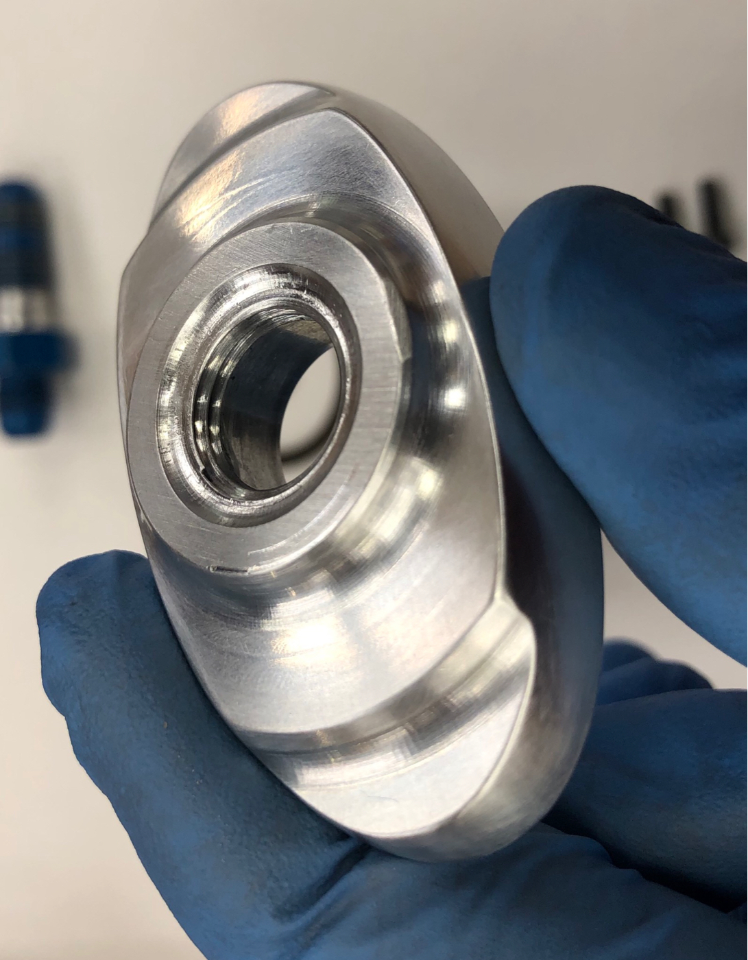
This shows the tank-contact faces of both flanges. Note small bores in the outer flange face where the cap screw heads reside. These screws secure the inner flange permanently to the tank inner wall and impart anti-rotation force to both outer and inner flanges during tightening or removal of the hollow bolt. After torquing, the screws serve to prevent any possible rotation of the entire assembly:
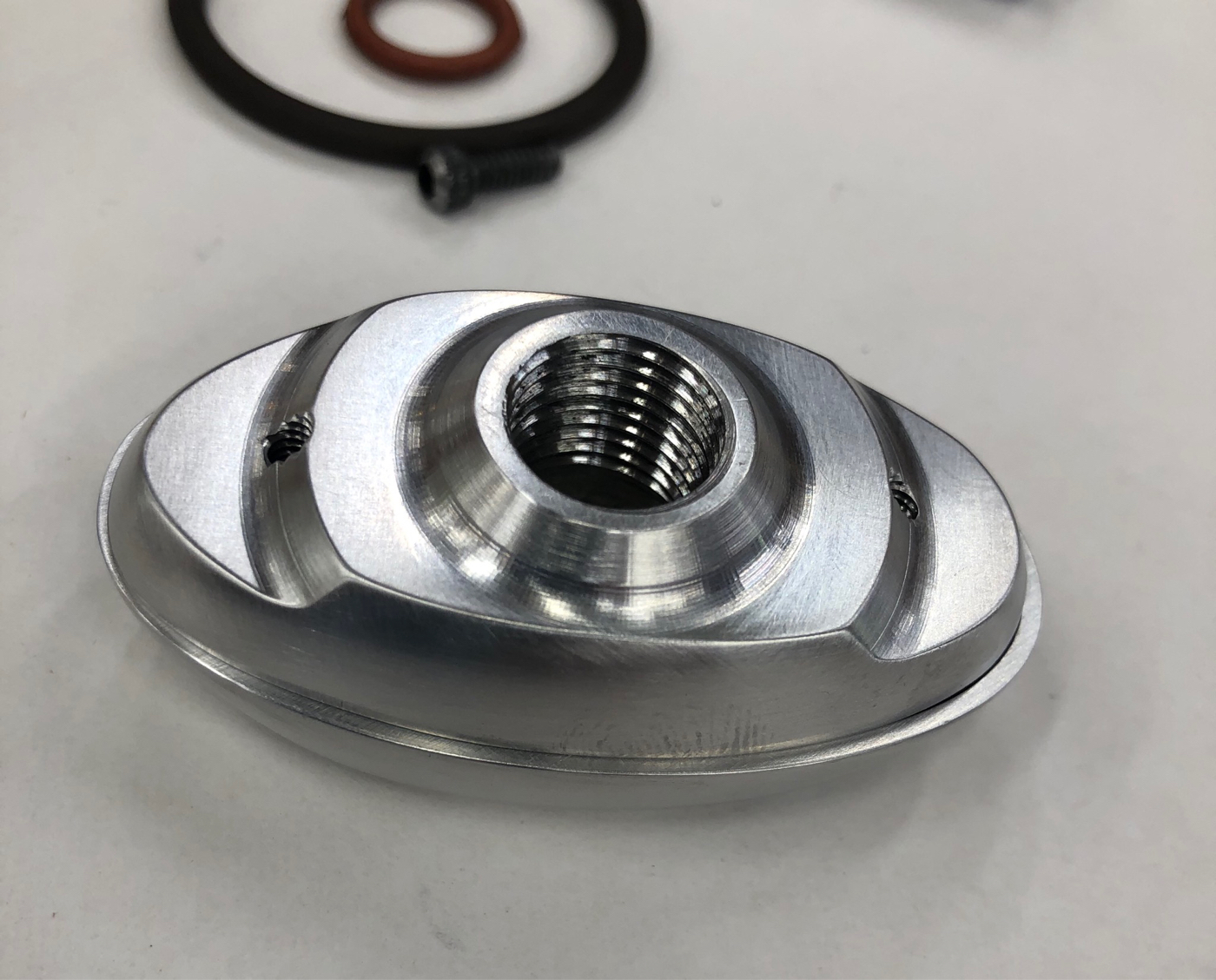
The rigid inner flange is fully threaded and acts as very sturdy nut for the hollow bolt. Here it is shown stacked upon the outer flange. Note that the outer dimension of the inner flange exceeds that of the large elliptical O-ring groove that is cut into the outer flange. This prevents any distortion of the tank wall when torqued:
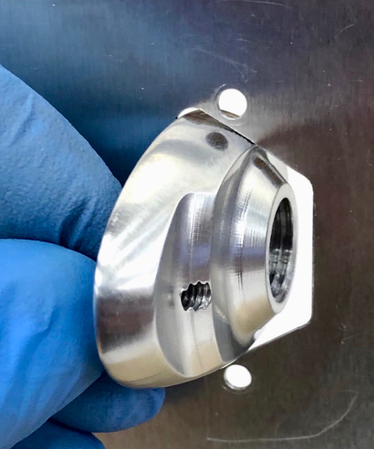
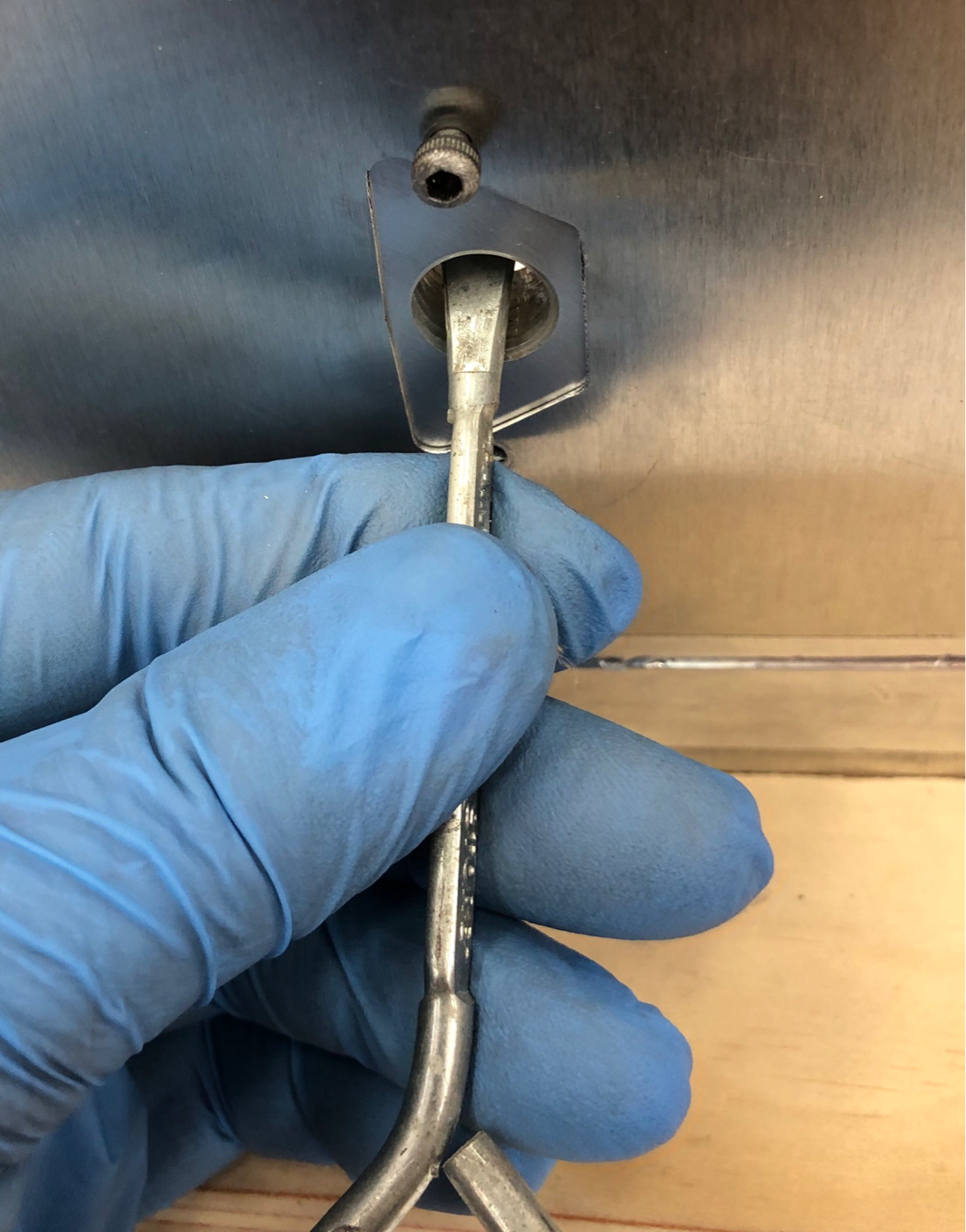
This shows the Inner flange being inserted through the trapezoidal hole in the tank mockup and placed in approximate position using one of the cap screws as a temporary handle. A 4’ piece of dental floss threaded through the central hole with both ends hanging outside tank would allow retrieval if dropped inside the tank by accident:
A paint can opener is being used here to hold the inner flange against the inner tank wall as the temporary screw is removed then re-inserted in its permanent hole through the tank skin:
The inner flange fully installed- there is never again a need to remove it:
https://media.fotki.com/2v2EjsgrMxBELK5.jpg
An O-ring groove is cut into the 6AN bulkhead fitting that serves as a hollow bolt, and some upper threads are also removed(the patent application provides for a custom-fabricated hollow bolt as well):
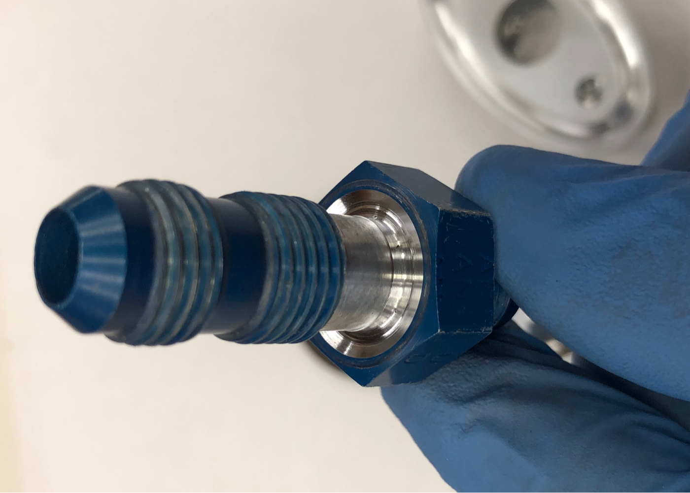
A few threads are cut into the outer flange bore to prevent the O-ring from extruding along shaft when torqued, but the flange spins freely on the fitting once screwed all the way on. This free-rotation becomes important during final assembly.
Both O-rings shown installed on the outer flange and the hollow bolt:
The outer flange shown installed to finger-tight O-ring contact, after taking care that the cap screw heads have entered into their bores note the gaps that will be closed upon torquing the assembly:
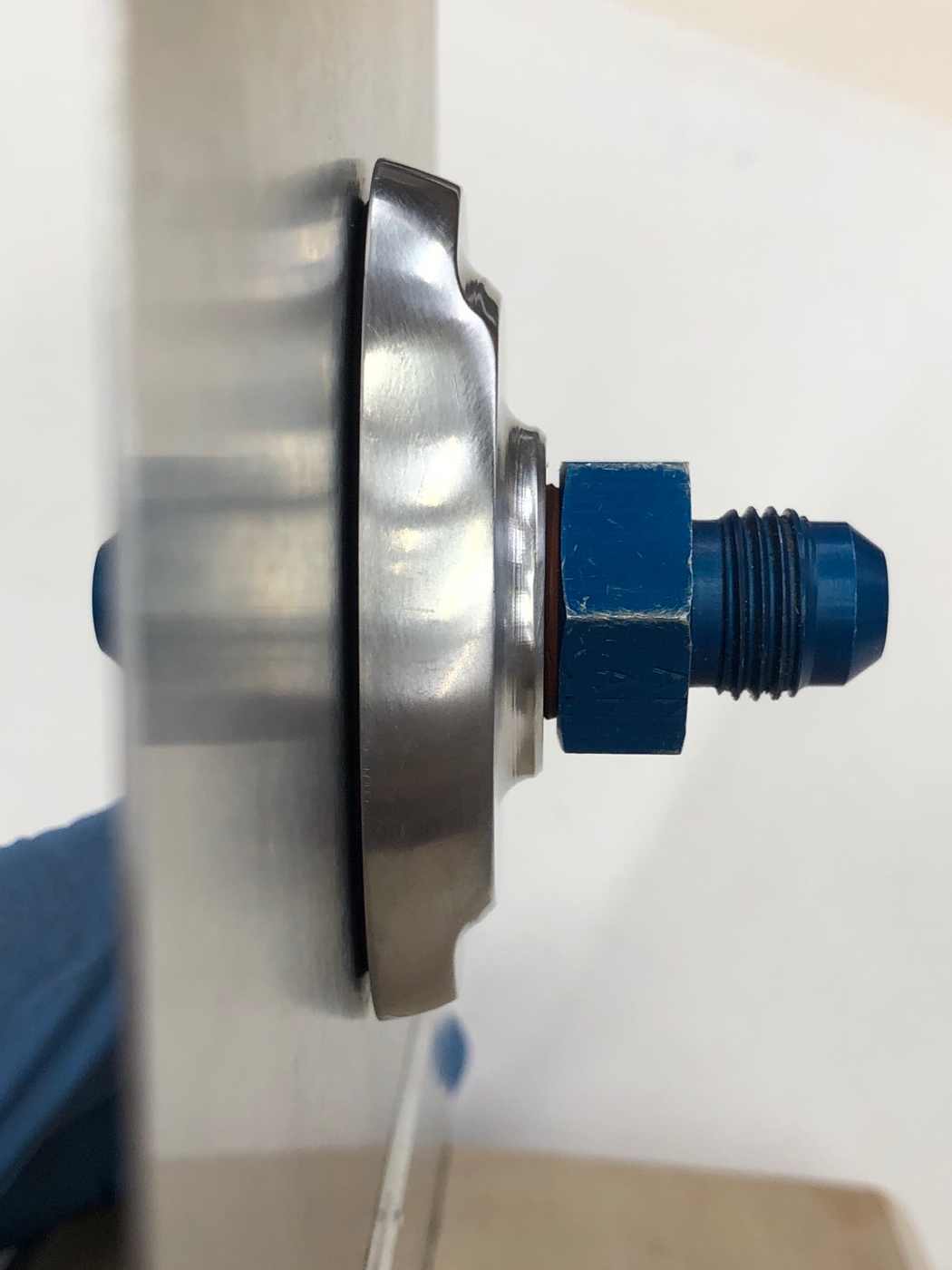
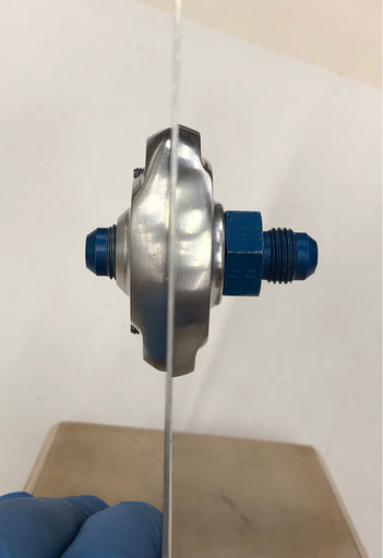
Finally, metal-to-metal contact is achieved as both O-rings are compressed during torquing of the bulkhead fitting onto the tank skin mockup. The unit is now fully operational and ready for installation of the return
Necessity really is the mother of invention. I've been pondering the challenge of retro- fitting fuel return lines to RVs and other aircraft for over two years. Those for my RV-7A need to be installed without removal of wings or tanks, and no access to the tank interior is possible without violating the difficult-to-access and heavily pro-sealed mid-cord sending unit flange . I’ll be posting a separate thread titled “Reasons you might need fuel return lines” soon.
I thought through several possible designs and I even prototyped a couple, but none were particularly satisfying. Then, about six months ago, Inspiration led to a design so elegant, easy, and reliable that It deserved protection, so I engaged an attorney and obtained US Provisional Patent #62/900,809. This new fitting can be used to add a fluid or gas line anywhere on any thin-walled tank with limited wall curvature, even where zero access to the tank interior is possible.
Right now I’m putting out feelers for a*production and marketing partner with CNC milling capabilities in order to offer this to the aircraft market (and the auto racing after-market?). Ironically, developing this idea has set back work on my own RV mods by about three months, but I hope that, in the end, others will benefit.
At this moment, working prototypes are at the anodizer(two for installation in my 7A and two as demo units), and I’ll soon be working on an installation video that I plan to share on VAF. Below are some preliminary photos. Note that these make use of some unfinished parts, so you will see some roughness in ring grooves and surface finish. A damaging fire at one of my properties has brought a pause to normal life, but I wanted to get the word out on this hopefully “coming soon” retrofit option. Before long I will update with more info, imagery of fully finished parts, and an installation video.
Features:
1- It is quick and easy. It can be installed in an RV in about one hour per side working within the space available between the wing and fuselage. The circular stiffener pressed into the forward root rib near the leading edge provides an ideal installation location.
2- Installation requires ZERO access to the tank interior, except through a small opening made entirely by working from outside the tank. The product kit will include an installation template that will be secured in place with aluminum tape to enable precise, easy cutting of this opening using a tiny carbide burr on a Dremel tool, and will include hole-locators for the two 3/32” retaining cap-screws. I’ve developed an installation strategy that keeps the tank interior absolutely clean during installation that will also be covered in the video.
3- The assembly includes rigid inner and outer flanges that sandwich the tank wall very firmly, preventing any significant strain upon it once installed.
4- It does not require the use of Pro Seal or any other type of sealants, relying instead upon Viton O-rings embedded in each face of the outer flange. It can be placed in service immediately.
5- It is permanent, yet can be easily removed for inspection and servicing in less than one minute if desired. (Plus one safety wire if desired but this is not required as it is intrinsically self-locking).
6- It promises extreme reliability and airworthiness.
7- *It is cosmetically beautiful, with no connectors other than the AN flair fitting visible from outside the tank(more a factor for high-wings with visible tank ends than for RVs).
8- Many, including me, might actually install it in new builds as well as retrofits and for feed lines as well as return lines, especially in aircraft with visible tank ends. Using one for feed-lines would provide for the very easy servicing of a finger screen on the pickup line inside the tank. Photos follow here:
This shows all of the parts, including a tank cutout mock-up. The working name is the “0tis elipt0flange” tm, patent pending #62/900,809:
This shows the tank-contact faces of both flanges. Note small bores in the outer flange face where the cap screw heads reside. These screws secure the inner flange permanently to the tank inner wall and impart anti-rotation force to both outer and inner flanges during tightening or removal of the hollow bolt. After torquing, the screws serve to prevent any possible rotation of the entire assembly:
The rigid inner flange is fully threaded and acts as very sturdy nut for the hollow bolt. Here it is shown stacked upon the outer flange. Note that the outer dimension of the inner flange exceeds that of the large elliptical O-ring groove that is cut into the outer flange. This prevents any distortion of the tank wall when torqued:
This shows the Inner flange being inserted through the trapezoidal hole in the tank mockup and placed in approximate position using one of the cap screws as a temporary handle. A 4’ piece of dental floss threaded through the central hole with both ends hanging outside tank would allow retrieval if dropped inside the tank by accident:
A paint can opener is being used here to hold the inner flange against the inner tank wall as the temporary screw is removed then re-inserted in its permanent hole through the tank skin:
The inner flange fully installed- there is never again a need to remove it:
https://media.fotki.com/2v2EjsgrMxBELK5.jpg
An O-ring groove is cut into the 6AN bulkhead fitting that serves as a hollow bolt, and some upper threads are also removed(the patent application provides for a custom-fabricated hollow bolt as well):
A few threads are cut into the outer flange bore to prevent the O-ring from extruding along shaft when torqued, but the flange spins freely on the fitting once screwed all the way on. This free-rotation becomes important during final assembly.
Both O-rings shown installed on the outer flange and the hollow bolt:
The outer flange shown installed to finger-tight O-ring contact, after taking care that the cap screw heads have entered into their bores note the gaps that will be closed upon torquing the assembly:
Finally, metal-to-metal contact is achieved as both O-rings are compressed during torquing of the bulkhead fitting onto the tank skin mockup. The unit is now fully operational and ready for installation of the return
Last edited by a moderator:
")

