Rotax has made several changes to the Ducati Voltage Rectifier Regulator over the years. There are at least three versions, all with unique part numbers. The two most recent versions are found in the RV-12, and both have had unacceptable failure rates. The two versions have different failure modes. It?s important to separate the two when looking for a solution, as a fix for one version may have no effect on the other. Rotax P.N. 365-347 ( Ducati P.N. 343620) this was manufactured until 2009, and was replaced by Rotax P.N. 365-349 (Ducati P.N. 362001.) Based on the timing of the redesign, it may have been component obsolescence, not reliability issues, that drove the change.
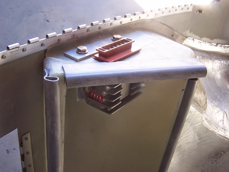
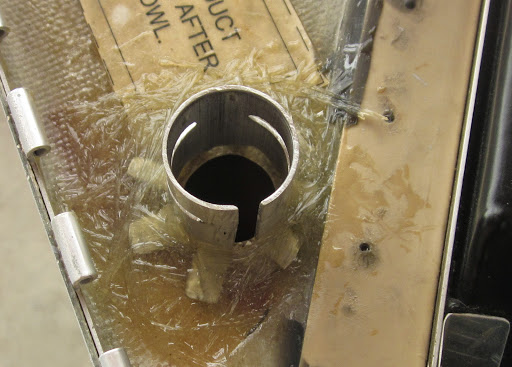
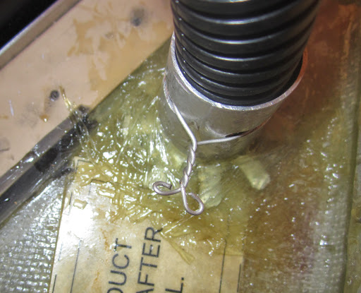
First we will look at P.N. 343620, we reference the Ducati P.N. because this number is stamped in the top of the regulator, also found here is it?s four digit date code. This version is similar to older versions in its choice of power component packages. The Regulator?s power output circuit utilizes a full wave bridge with SCRs in half the bridge that act as a switch to turn the bridge on and off. The positive half of the bridge uses two power diodes in a leadless package called a ?button case,? the cathode side of the button is soldered directly to a copper plate and a lead soldered is to the other side of each diode. The plate is electrically insulated from the regulator case with a thermally conductive silicone pad. The assembly is held to the case with one insulated screw. The negative half of the bridge consists of two power SCRs. The anode tab of the SCRs TO-220 package is screwed (grounded) to the case, with thermal joint compound applied. Leads from the diode plate assembly, the SCRs and the ground connection are soldered to the bottom of a control PCB mounted in the case. The case is filled with a thermal potting compound. Its hardness is 85 Shore A. The common failure point with this version is the separation of a diode from the copper plate. The diode assy. generates about 30W of heat, at full output. Increased thermal resistence from both the silicone insulator and poor plate fit, may not permit enough heat transfer to the case at peak power output. Each SCR can generate almost 25W of heat, no failures of the SCRs or SCR leads were observed.
The current production regulator is P.N. 362001. This version incorporates several changes including modifications to the cutoff voltage circuit on the control PCB and the replacement of the obsolete ?button case diode assembly? with a leaded, bridge rectifier package. There are no changes to the regulator housing from older versions. The bridge rectifier package screws to the case using the same screw hole from the old ?button diode assembly? plate. The bridge rectifier package is installed with thermal joint compound under it. The Regulator uses the positive half of the bridge rectifier package in its power output bridge, and the negative half of this package is used to supply a negative voltage reference to the control PCB. The negative half of the power output bridge uses the same power SCRs as the previous version regulators. Again the SCR leads, bridge rectifier leads and ground lead solder to the bottom of control PCB in the regulator housing. The case is filled a new gel type thermal potting compound. Its hardness is 60 Shore A. The common failure point in this version is SCR lead separation at the PCB or lead shearing at the SCR body. Some fretting was also observed at the bridge rectifier solder connections on the PCB. The SCR design and mounting have not changed from the previous version, so the cause of the failures may be related to the new gel type potting compound. The change to a bridge rectifier package, with its improved heat sinking, seems to resolve the diode to plate failure issues associated with the earlier version regulator.
link to Rotax P.N. 365-347 / Ducati P.N. 343620 internal schematic and assembly (3-page PDF file)
https://drive.google.com/file/d/0ByPxADyU-DwPdTQ3NWp5LW9iOHc/view?usp=sharing
Link to Rotax P.N. 365-347 / Ducati P.N. 343620 failure results
https://drive.google.com/file/d/0ByPxADyU-DwPZGM4c1dYRlc0MTg/view?usp=sharing
link to Rotax P.N. 365-349 / Ducati P.N. 362001 internal schematic and assembly (4-page PDF file)
https://drive.google.com/file/d/0ByPxADyU-DwPWTBBcGlUeENTcHc/view?usp=sharing
link to Rotax P.N. 365-349 / Ducati P.N. 362001 failure result photos
https://drive.google.com/file/d/0ByPxADyU-DwPYm1rYUVsbUJyQ3M/view?usp=sharing
--------------------------------
12/2016 update
Below are links to 3D models of the regulator assembly, these files are only viewable in Solidworks. Members of EAA can download a free copy of the student edition of Solidworks as one of there EAA member benefits. Go to the EAA website for more info.
Solidworks 3D model of Rotax Regulator 965-349
https://drive.google.com/file/d/0ByPxADyU-DwPQmlIYndpWEh1MkU/view?usp=sharing
Solidworks 3D model of Rotax Regulator 965-347
https://drive.google.com/file/d/0ByPxADyU-DwPNEhOd2gwZFR6U3M/view?usp=sharing
Mike Miller


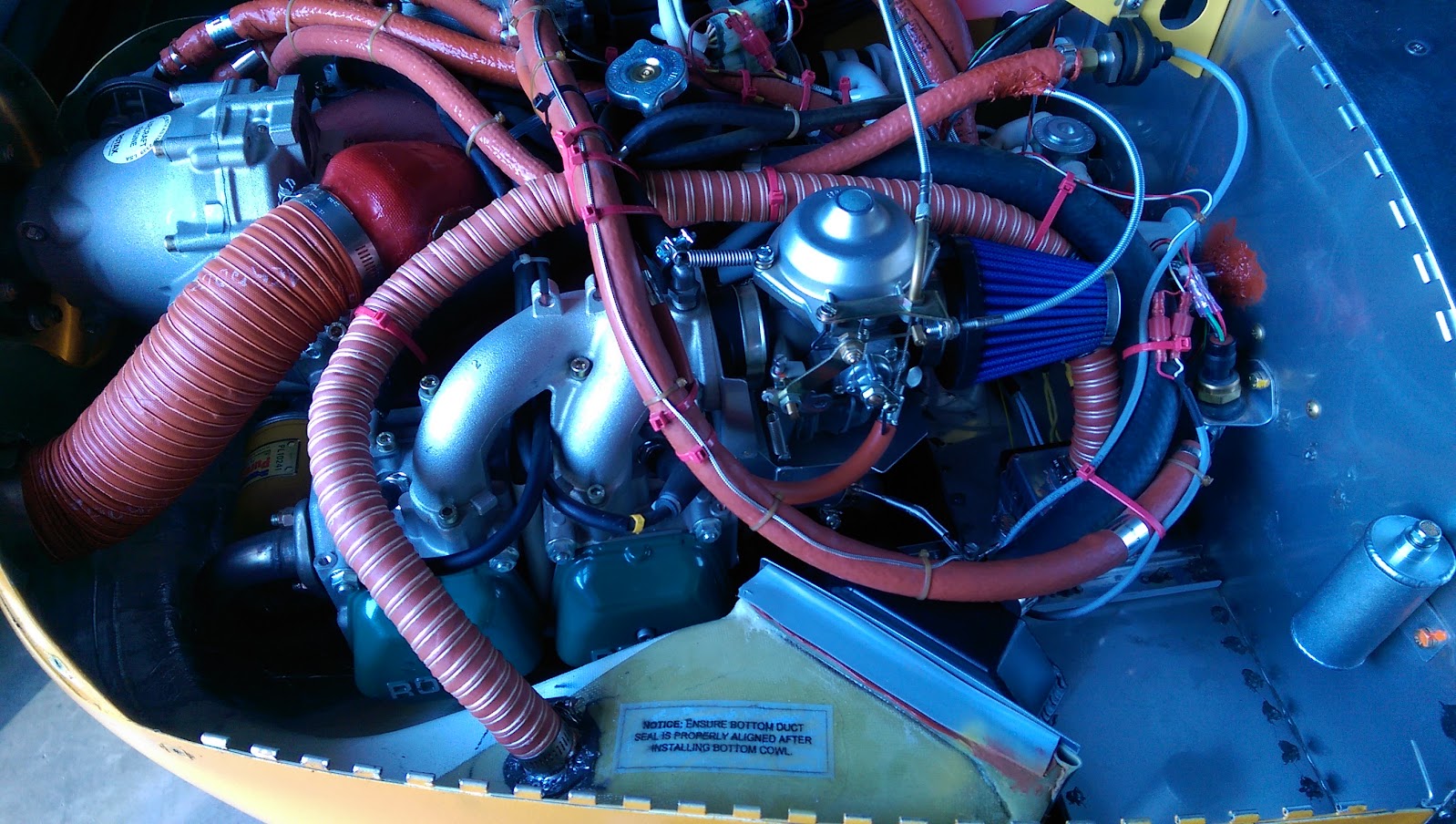
 At 133 hours HOBBS (one year since initial flight), I went out to fly today and my alternator/generator is no longer charging (battery voltage falling through 12.3 v with -7 amps at 5,300 rpm).
 (I was thinking of you when writing my initial response and saw it coming
  )
)") I was surprised to note how hot the VR gets - you cannot hold your hand on it for more than 5-10 seconds.
I was surprised to note how hot the VR gets - you cannot hold your hand on it for more than 5-10 seconds. ")