azrv6
Well Known Member
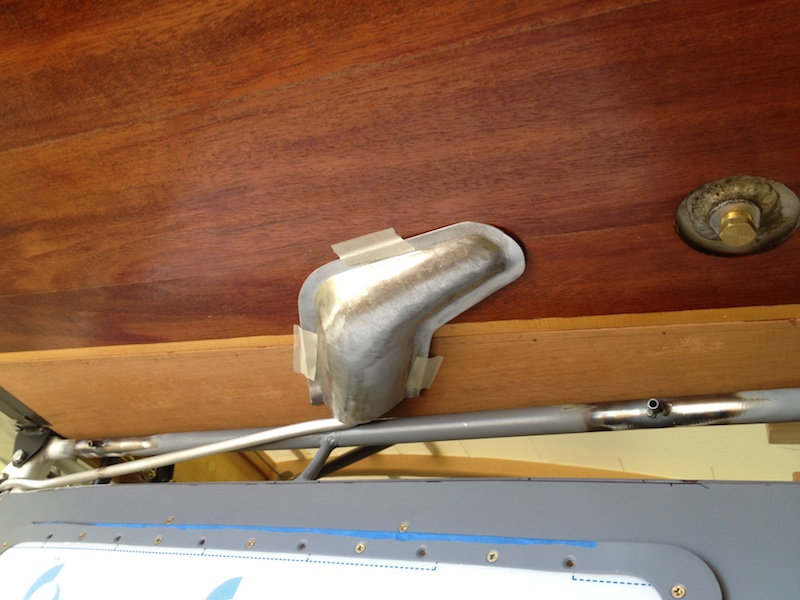
Not specifically RV related but hopefully useful. I had to make two complex fairings for the Monocoupe and had read and re-read Dan Horton's very useful thread on the subject and was fully prepared to pull out the fiberglassing materials and give it a go. Here is the area to be covered:
As you can see the gas tank outlet drops down out of the bottom of the wing and the gas line angles over towards the top of the fuselage and then moves forward. On some of the old 'Coupes this gas line just hangs out in the breeze. I have plenty of scrap aluminum at the hangar and decided to give hand forming a pair of fairings a try. Three hours later, here is the end result:
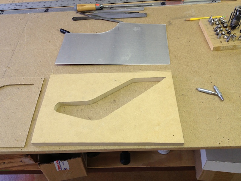
I started out by making a poster board pattern for the fairing - the outline on the bottom of the tank skin, this would represent the flange of the fairing. I cut that out on some 3/4" MDF, also cut out a 1/8" thick MDF matching piece. The aluminum gets sandwiched between these two pieces of MDF while hammer forming the bump in the fairing. This fairing has to meet up with the wing root fairing, so the part is longer than necessary and will be trimmed to match the wing root fairing.
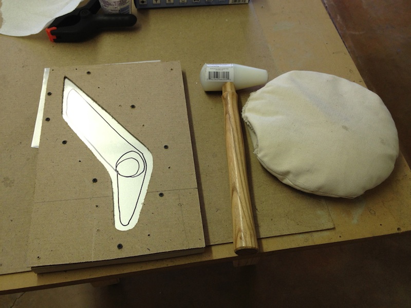
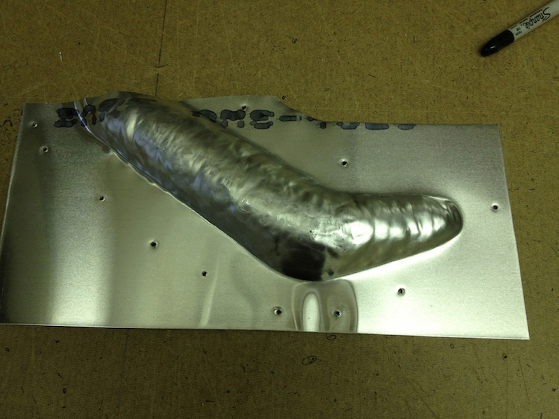
Aluminum sandwiched between the two pieces of MDF using screws that go through the aluminum to assure it doesn't move around during the violence about to happen, circled area gets the most crown and needs the most hammering. I bought the hammer at Harbor Freight for $11.99 (http://www.harborfreight.com/2-inch-teardrop-mallet-66205.html), and made my own beater bag. Sewn from canvas (duck), double thickness, 12" diameter, filled with sand. Ready to hammer. Put the aluminum over the beater bag and have at it:
Just a few minutes and the part is really starting to take shape. You can manage the height profile (or depth) by managing the hammer blows. Used both ends of the mallet depending on where the hammering was needed.
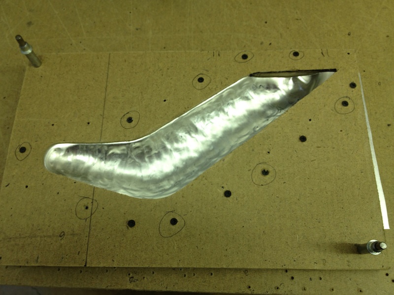
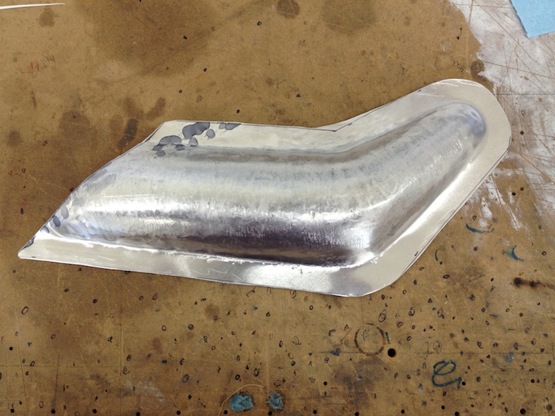
Most of the shaping is done now, and the part was taken out of the MDF form and ready for planishing. From here on out, as you planish, you will easily move the flange around, so you want to be careful and watch it closely.
About 30 minutes of planishing and then initial trim of the flange and the part is ready to fit up to the wing root fairing.
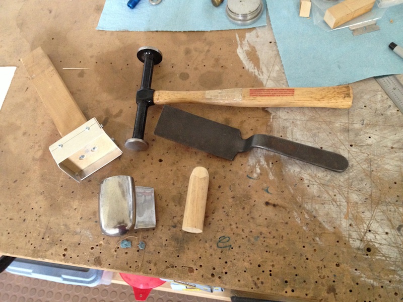
Here are the planishing tools used. Body dolly available from a variety of sources. Wood and aluminum part in the upper right is my way of turning the hand dolly into a "post dolly" so I can clamp it in the vise. Flat body hammer with two different sized flat (no crown) heads, almost exclusively use the smaller end. Steel slapper. Wood dowl with end shaped to help work the small tapered end. Oh yeah, not pictured, but very necessary, is hearing protection.
This was the first time I tried something like this. It was a pleasant surprise that I got these two complex shapes done in aluminum with about 5 hours total time, including making the patterns and cutting the MDF. One part was made from 3003H14 0.040", annealed before hammering. The other part made from 6061-0 0.040". Decision making process on this was the MOH (material on hand).
As you can see the gas tank outlet drops down out of the bottom of the wing and the gas line angles over towards the top of the fuselage and then moves forward. On some of the old 'Coupes this gas line just hangs out in the breeze. I have plenty of scrap aluminum at the hangar and decided to give hand forming a pair of fairings a try. Three hours later, here is the end result:
I started out by making a poster board pattern for the fairing - the outline on the bottom of the tank skin, this would represent the flange of the fairing. I cut that out on some 3/4" MDF, also cut out a 1/8" thick MDF matching piece. The aluminum gets sandwiched between these two pieces of MDF while hammer forming the bump in the fairing. This fairing has to meet up with the wing root fairing, so the part is longer than necessary and will be trimmed to match the wing root fairing.
Aluminum sandwiched between the two pieces of MDF using screws that go through the aluminum to assure it doesn't move around during the violence about to happen, circled area gets the most crown and needs the most hammering. I bought the hammer at Harbor Freight for $11.99 (http://www.harborfreight.com/2-inch-teardrop-mallet-66205.html), and made my own beater bag. Sewn from canvas (duck), double thickness, 12" diameter, filled with sand. Ready to hammer. Put the aluminum over the beater bag and have at it:
Just a few minutes and the part is really starting to take shape. You can manage the height profile (or depth) by managing the hammer blows. Used both ends of the mallet depending on where the hammering was needed.
Most of the shaping is done now, and the part was taken out of the MDF form and ready for planishing. From here on out, as you planish, you will easily move the flange around, so you want to be careful and watch it closely.
About 30 minutes of planishing and then initial trim of the flange and the part is ready to fit up to the wing root fairing.
Here are the planishing tools used. Body dolly available from a variety of sources. Wood and aluminum part in the upper right is my way of turning the hand dolly into a "post dolly" so I can clamp it in the vise. Flat body hammer with two different sized flat (no crown) heads, almost exclusively use the smaller end. Steel slapper. Wood dowl with end shaped to help work the small tapered end. Oh yeah, not pictured, but very necessary, is hearing protection.
This was the first time I tried something like this. It was a pleasant surprise that I got these two complex shapes done in aluminum with about 5 hours total time, including making the patterns and cutting the MDF. One part was made from 3003H14 0.040", annealed before hammering. The other part made from 6061-0 0.040". Decision making process on this was the MOH (material on hand).