
Van's Air Force
You are using an out of date browser. It may not display this or other websites correctly.
You should upgrade or use an alternative browser.
You should upgrade or use an alternative browser.
Photos of EFI fuel return line routing?
- Thread starter SonexGuy
- Start date

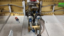
Kinda like this--but the hoses routed through the outboard spar brackets. Can use AN833-6D bulkhead fittings at the fuselage sides. This one has the filters on the pumps, and designed to use the stock valve and pump dog house cover.I don’t have pictures, but I can tell you that I have the duplex valve and routed my fuel return into the second bay of the selected tank.
Attachments
How about "where" the return lines penetrated the side of the fuselage? Where the fuel supply line goes through the fuselage, there are two pieces of aluminum, with an air gap between, so a bulkhead fitting would not seem to work in that location. My return fitting to the fuel tank is just below the fitting for the vent line.Kinda like this--but the hoses routed through the outboard spar brackets. Can use AN833-6D bulkhead fittings at the fuselage sides. This one has the filters on the pumps, and designed to use the stock valve and pump dog house cover.
Since nobody had any particular location or advice, I worked out where I thought it would work best. I ended up adding a similarly sized hole in the side of the fuselage, under the factory-located hole. Because I have an inverted tank on the left wing, so on that wing the RETURN line exits the TOP hole, and the SUPPLY line exits the BOTTOM hole. On the right side, the TOP (factory-located) hole is still the best place for the SUPPLY line, with the RETURN line through the BOTTOM hole. Here's my log entry for those holes, in case it helps someone else:

 eaabuilderslog.org
eaabuilderslog.org
eaabuilderslog.org
EAABuildersLog.org - Free aircraft builders log website.
EAABuildersLog.org is a airplane builders log website to store your projects on the web for free. The EAA (Experimental Aircraft Association, Inc.) provides this website for it's members for free..
eaabuilderslog.org
EAABuildersLog.org - Free aircraft builders log website.
EAABuildersLog.org is a airplane builders log website to store your projects on the web for free. The EAA (Experimental Aircraft Association, Inc.) provides this website for it's members for free..
eaabuilderslog.org
There are many ways to make these penetrations and depends on several factors. Probably why nobody responded. On the 14 the supply side penetration was fairly low and return fairly high. This was needed for the tunnel design for the 14. The 10 they were more parallel as they had to pass under the seat. I'm sure you took your designs needs and made the appropriate choice. One question in one set of pictures it appears you used grommets as pass-throughs (which I would not recommend) and the other it appears you used bulkhead fittings (which I would recommend) for pass throughs. Just my 2 cents and I'm sure you have thought through the different options.Since nobody had any particular location or advice, I worked out where I thought it would work best. I ended up adding a similarly sized hole in the side of the fuselage, under the factory-located hole. Because I have an inverted tank on the left wing, so on that wing the RETURN line exits the TOP hole, and the SUPPLY line exits the BOTTOM hole. On the right side, the TOP (factory-located) hole is still the best place for the SUPPLY line, with the RETURN line through the BOTTOM hole. Here's my log entry for those holes, in case it helps someone else:
EAABuildersLog.org - Free aircraft builders log website.
EAABuildersLog.org is a airplane builders log website to store your projects on the web for free. The EAA (Experimental Aircraft Association, Inc.) provides this website for it's members for free..EAABuildersLog.org - Free aircraft builders log website.
EAABuildersLog.org is a airplane builders log website to store your projects on the web for free. The EAA (Experimental Aircraft Association, Inc.) provides this website for it's members for free..
we typically like the return hole in the side skin to be above the supply hole. For those NOT use and inverted fuel pick up, this makes the hoses my symetrical.Since nobody had any particular location or advice, I worked out where I thought it would work best. I ended up adding a similarly sized hole in the side of the fuselage, under the factory-located hole. Because I have an inverted tank on the left wing, so on that wing the RETURN line exits the TOP hole, and the SUPPLY line exits the BOTTOM hole. On the right side, the TOP (factory-located) hole is still the best place for the SUPPLY line, with the RETURN line through the BOTTOM hole. Here's my log entry for those holes, in case it helps someone else:
EAABuildersLog.org - Free aircraft builders log website.
EAABuildersLog.org is a airplane builders log website to store your projects on the web for free. The EAA (Experimental Aircraft Association, Inc.) provides this website for it's members for free..EAABuildersLog.org - Free aircraft builders log website.
EAABuildersLog.org is a airplane builders log website to store your projects on the web for free. The EAA (Experimental Aircraft Association, Inc.) provides this website for it's members for free..
Mike, are you using the Airflow Performance purge valve? They have pretty good documents on their site that could help...
No. It's not part of the UL Power fuel system. Excess fuel is constantly returned to whichever tank the duplex fuel selector valve is set on.Mike, are you using the Airflow Performance purge valve? They have pretty good documents on their site that could help...
The bulkhead fittings are only for the supply and return lines where they pass through the firewall. All my fuel lines are braided hose. The RV-7 standard is to use the supplied rubber grommets for the aluminum fuel lines, but there are two layers of skin/structure to go through on each side of the fuselage, so I'm opting for a grommet in each skin/structure (8 required for 4 holes). The ones supplied by Vans are OK for aluminum fuel lines that exit the fuselage perpendicular to the fuselage skin, but the braided lines take a more direct, angled path to the wing fittings, so the alternate grommets I'm using allow for that.There are many ways to make these penetrations and depends on several factors. Probably why nobody responded. On the 14 the supply side penetration was fairly low and return fairly high. This was needed for the tunnel design for the 14. The 10 they were more parallel as they had to pass under the seat. I'm sure you took your designs needs and made the appropriate choice. One question in one set of pictures it appears you used grommets as pass-throughs (which I would not recommend) and the other it appears you used bulkhead fittings (which I would recommend) for pass throughs. Just my 2 cents and I'm sure you have thought through the different options.
The added holes are below the standard hole locations, as the fuel lines are coming from near the floor, not near the top of the spar tunnel.
