Van's Air Force

The definitive Van's Aircraft support community! Buying, building or flying an RV? Join our exclusive family of mentors and enthusiasts!

Stuffing an IO-360-Axxx or IO-390-A,C [EXP119,124] into a Pink Cowl

bjdecker

Well Known Member
Ambassador
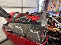
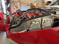
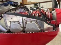
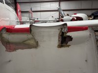
Ok gang -- has anyone successfully* mounted an IO-360-Axxx or IO-390-A,C on their RV-7/7A with a Pepto Pink Cowl? I thought I had this nailed, but the #1 cylinder & baffling keeps bumping/chafing against the cowling right at the "cove" that's cutout of the top cowl. My cowl is set 3/16" behind and in line the spinner+bulkhead.

(*Success in this case means No rubbing/bumping...)

I am considering throwing the whole thing into the trash and ordering a new "grey gelcoat" variant - but wanted some data from the field.

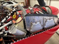
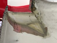
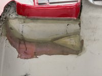
For what it's worth, the old green/yellow cowl on my last RV-7 (with the same engine) fit perfectly, without any interference. (Picture attached - rub area circled in Red)Attachment.jpeg

Things I've already done:

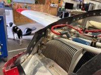
1. Lowered the side wall baffle on #1.
2. Ground down the screw boss "ear" on the #1 cylinder
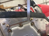
3. Changed from AN960-416 to 416L washer under the baffle hold down screw.

I could fabricate a "blister" into the top cowl, like something from a Cessna 190 cowl, but that seems wrong...

Open to suggestions from the hive mind...
 
Last edited:
Post a pic of the cyl baffle area, so we might make suggestions for addressing the issue there.
 
IMG_1791.jpeg

Area circled in yellow — lowered by another 1/2” aft of the forward cylinder head screw. I don’t have a photo of current condition, but there is about 1” between top cowl and the area circled in yellow - it still bumps during start-up and shut down.
 
Barring a great idea from the hive mind, you could do a blister which actually looks fine. Just make it over a fairly large area so that it blends in well. I did an extreme version of that with my -6 with the original polyester cowl to stuff an AV engine into it. Use pour foam to make the male blister instead of that spray foam as I did.

1777657204501.jpeg1777657219860.jpeg1777657246933.jpeg1777657266635.jpeg
 
I seem to recall seeing an angle valve with the side baffle wall on the inboard side of the 1/4-20 cylinder head tabs. I figured I'd try it someday.

The cowl bumping issue exists on the RV-8. I've been flying this configuration for quite a while now. The plenum "soft spots" (gray) are 9oz glass impregnated with Permatex UltraBlack silicone. Roll it onto the glass between two 4 mil plastic sheets.

There is no side baffle wall above the ears on #1 and #2. The fiberglass plenum is attached directly to the ears. The aluminum plates above the valve covers are clamp plates. They merely keep the plenum from bowing outward between the ears.

Plenum Soft Spot left.jpg

Plenum Soft Spot right.jpg
 
I seem to recall seeing an angle valve with the side baffle wall on the inboard side of the 1/4-20 cylinder head tabs. I figured I'd try it someday.

The cowl bumping issue exists on the RV-8. I've been flying this configuration for quite a while now. The plenum "soft spots" (gray) are 9oz glass impregnated with Permatex UltraBlack silicone. Roll it onto the glass between two 4 mil plastic sheets.

There is no side baffle wall above the ears on #1 and #2. The fiberglass plenum is attached directly to the ears. The aluminum plates above the valve covers are clamp plates. They merely keep the plenum from bowing outward between the ears.

View attachment 116473

View attachment 116474
Hey Dan - Off topic, but what made you decide on nut plates vs Skybolts for the horizontal cowl join? Looks neat.
 
I have an IO-360-A1A in a pink cowl in my RV-8.

I don't have a plenum, I just have baffle seals. I don't really know if I get momentary bumps. If I do get occasional contact, it leaves a black scuff, not a gouge like your pictures show from vibratory contact, not just momentary bumps.

I do not have an inch from the edge of the cylinder head baffle to the cowl, probably 5/8". I Can say that my cylinder head baffles are trimmed down to a lower height than depicted in your photo in post #5.

If you have an inch gap and still get contact, I wonder if you might consider firmer Lord mounts. I think the "aerobatic" mounts are stiffer, so you would get less engine motion on shut-down.
 
Hey Brian- it seems odd that there would be that much of a difference between the pink and grey cowls. I guess I assumed they came out of the same mold, but maybe not.

I've got a 390 and the grey cowl. My baffling looks pretty much the same as yours in that area and it doesn't rub. So take that as an endorsement that yeah, it will work with a gray cowl if you decide to go with the nuclear option and just fix this with the checkbook.

If you're at the point of ordering a new cowl anyway, it seems like it wouldn't hurt anything to put a blister in this one first and see if you can live with it. Doesn't look like it would take much, I'd reckon that 3/8" would probably do it and if you feather it in over a large enough area I doubt that anybody but you would ever notice.

edit; now that I think about it, if you've got one inch of clearance there static it seems like thats an awful lot of flopping around. I'm familiar with the lycoming wet dog shake, but still...What sort of shape are your engine mounts in? Are they the fancy lord mounts with vibration damping fluid? I've just got the solid Berry mounts, so that might make a difference as well? I dunno, but it's something to think about.
 
Last edited:
Hey Dan - Off topic, but what made you decide on nut plates vs Skybolts for the horizontal cowl join? Looks neat.
Two reasons.

Not enough clearance for Skybolts on the left side. The nutplate over #4 actually has a nylon wear plate on each side so it doesn't eat a hole in the valve cover.

I wanted a full flange for a relatively air tight seam. Any seam which leaks high pressure air is a drag producer.
 
Two reasons.

Not enough clearance for Skybolts on the left side. The nutplate over #4 actually has a nylon wear plate on each side so it doesn't eat a hole in the valve cover.

I wanted a full flange for a relatively air tight seam. Any seam which leaks high pressure air is a drag producer.
Wouldn't that seam be on the lower pressure side of the cowl internals? I suppose it's still higher than ambient though. Never mind, it's above my head. :ROFLMAO: :ROFLMAO:
 
@scsmith Steve - thanks; The -7 and -8 cowls are different across the inlets (weird huh…)

@Desert Rat - Yeah it’s a flipper for sure, but it doesn’t droop or rise with G loads - just rotates about the longitudinal axis. Motor mounts are still “new” at 382 hours now, but it’s done this since birth…
 
Two reasons.

Not enough clearance for Skybolts on the left side. The nutplate over #4 actually has a nylon wear plate on each side so it doesn't eat a hole in the valve cover.

I wanted a full flange for a relatively air tight seam. Any seam which leaks high pressure air is a drag producer.
Sorry for continuing a thread drift - just wanted to reinforce what DanH said. When we prep Bob Mills' Rocket-6 for pylon racing, we tape over all the seams. The biggest payoff is at the cowl. We think we get 2--3 kts from taping.

Using piano hinge along the side joint of the cowl creates a pretty good seal though - you set the hinge a little above the split line, so the solid portion of the lower half of the hinge, not the 'fingers', is adjacent to the split line.
 
Thanks Scott - I guess I’ll save some $$$ and start hacking more material away from the #1 baffle side wall…
You may try modifying your plenum. Hard to see witness marks in pic. I have an idea to modify the plenum, but need to know the part rubbing. can you post a pic that more clearly identifies the exact piece that is rubbing? This would be way easier tha FG work.
 
You may try modifying your plenum. Hard to see witness marks in pic. I have an idea to modify the plenum, but need to know the part rubbing. can you post a pic that more clearly identifies the exact piece that is rubbing? This would be way easier tha FG work.
Thanks Larry - unfortunately I am out of pocket for a while, so no pictures :(

The portion of the baffle/plenum attachment that’s rubbing/touching the top cowl is the corner of the baffle wall, baffle doubler “dog bone”, and top clamping strip of the plenum cover, right along the top between the two large hold down screws ~23.5” forward of the firewall cowling flange.

The rework I have in mind now is to lower this corner/edge stack up by another .063” - .090”…
 
I fit a -390 front governor, large front bearing in my stock -7 pink cowl just fine. Used the -14 baffles. Plenty of cutting height off the baffles but no issues with fit or rubbing.
 
Last edited:
I fit a -390 front governor, large front bearing in my stock -7 pink cowl just fine. Used the -14 baffles. Plenty of cutting height off the baffles but no issues with fit or rubbing.
I'd love to see pictures of the right side of the engine (#1 and #3 cylinders) when you get a chance.
 
I'd love to see pictures of the right side of the engine (#1 and #3 cylinders) when you get a chance.

Here ya go. No rubbing. Inner cowl could have been cleaner but it was done on a painted airplane, and I hate painting. The inlet ramp on the right side had to be moved back quite a bit from the previous instillation. The CHT’s are within 5 degrees in most phases of flight.
 

Attachments

  • IMG_5552.jpeg
    IMG_5552.jpeg
    3.8 MB · Views: 25
  • IMG_5551.jpeg
    IMG_5551.jpeg
    4.5 MB · Views: 25
  • IMG_5550.jpeg
    IMG_5550.jpeg
    4.5 MB · Views: 19
  • IMG_5549.jpeg
    IMG_5549.jpeg
    4.3 MB · Views: 16
  • IMG_5548.jpeg
    IMG_5548.jpeg
    3.9 MB · Views: 18
  • IMG_5547.jpeg
    IMG_5547.jpeg
    4.1 MB · Views: 17
  • IMG_5546.jpeg
    IMG_5546.jpeg
    3 MB · Views: 17
  • IMG_5545.jpeg
    IMG_5545.jpeg
    3.2 MB · Views: 16
  • IMG_5544.jpeg
    IMG_5544.jpeg
    3.1 MB · Views: 26
Back
Top