Van's Air Force

The definitive Van's Aircraft support community! Buying, building or flying an RV? Join our exclusive family of mentors and enthusiasts!

Cowl Clearance Conundrum

yahugh

Member
Patron
I know this isn't strictly a propeller question but this is the closest forum I could find.

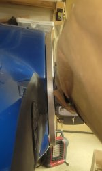
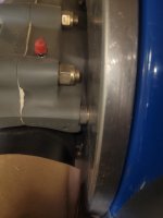
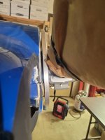
I'm attempting to adapt a cowl that was originally trimmed to fit an RV-7 with a Subaru engine and fixed-pitch prop to a newly installed O-360 with a constant-speed prop. (See here for background.) My problem is that the fit is almost perfect...but not quite. The clearance between the front flange of the cowl and the spinner varies between 13/64" and 1/16", the latter being less than the Van's "absolute minimum" 1/8".

What to do? Here are the options I've considered.
  • Fly with it as-is. Probably a bad idea. Van's doesn't spec 1/8" minimum for no reason.
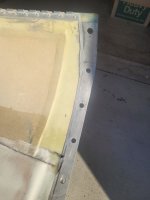
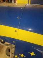
  • Trim the back of the cowl. This isn't a great option for reasons which should be clear from the attached pics.
  • Extend the prop out by 1/16". This doesn't seem feasible, though I could be wrong.
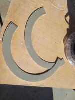
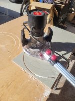
  • Grind down the front flange by 1/16", adding some backing material to maintain strength. I'm leaning towards this.
What say ye venerable builders?
 

Attachments

  • 20260111_205607.jpg
    20260111_205607.jpg
    448.5 KB · Views: 168
  • 20260110_082558.jpg
    20260110_082558.jpg
    1.4 MB · Views: 166
  • 20260109_173837.jpg
    20260109_173837.jpg
    1.1 MB · Views: 166
Last option.
I did pretty much the same in fitting my -7 cowl. The forward cowl flanges never light up very well.
I ground off the front flanges. THen glassed in new flanges to fit. Has worked great.
 
BTW, that 1/8" gap is a good call.
You will be surprised how much the engine and prop can move around. Particularly at start up.
The gap also makes cowl removal and install easier.
 
Is it possible to move your entire engine out 1/8 to 1/4 ? Personally, I would be reluctant to grind the face of that cowling off. Sounds like from other posters it’s been done, but you would definitely want that to be structurally brought back to its original strength.
 
Is it possible to move your entire engine out 1/8 to 1/4 ? Personally, I would be reluctant to grind the face of that cowling off. Sounds like from other posters it’s been done, but you would definitely want that to be structurally brought back to its original strength.
He needs an engine shrinker not engine stretcher.
 
You might be able to move the spinner forward relative to the prop. Assuming it's the stock mounting kit, that spacer between the spinner bulkhead (backing plate) and the prop is 0.250". You can swap those spacers for 0.125" spacers or 2x 0.063" washers (this 0.125" is the absolute minimum to clear the hub mounting location spot faces), though you may need to reprofile the bulkhead inner profile in order to ensure adequate hub clearance; you'll also need to worry about blade trailing edge clearance at high pitch.
 
You might be able to move the spinner forward relative to the prop. Assuming it's the stock mounting kit, that spacer between the spinner bulkhead (backing plate) and the prop is 0.250". You can swap those spacers for 0.125" spacers or 2x 0.063" washers (this 0.125" is the absolute minimum to clear the hub mounting location spot faces), though you may need to reprofile the bulkhead inner profile in order to ensure adequate hub clearance; you'll also need to worry about blade trailing edge clearance at high pitch.
This!

Carl
 
Is it possible to move your entire engine out 1/8 to 1/4 ? Personally, I would be reluctant to grind the face of that cowling off. Sounds like from other posters it’s been done, but you would definitely want that to be structurally brought back to its original strength.
One of my local builder buddies had that idea as well, but neither of us had any clue as to how to go about doing that.
 
You might be able to move the spinner forward relative to the prop. Assuming it's the stock mounting kit, that spacer between the spinner bulkhead (backing plate) and the prop is 0.250". You can swap those spacers for 0.125" spacers or 2x 0.063" washers (this 0.125" is the absolute minimum to clear the hub mounting location spot faces), though you may need to reprofile the bulkhead inner profile in order to ensure adequate hub clearance; you'll also need to worry about blade trailing edge clearance at high pitch.
Wow, what a great idea! I'll look into this.
 
So a Cessna 172 comes with big round washers about 1/8" thick that go between the engine and the engine vibration isolator. I did an engine change and one lower mount (from the factory) had two washers. I have since experimented with this and it's quite easy to put in the extra washer after the fact to get the 1/8" clearance required. I looked around at numerous 172's and there was almost always 1/8" clearance, but quite a variety of 'straight' vs. slightly offset L&R and up and down.
 
I had to go the cowl mod route when I changed props (Hartzell to MT). Heavily reworked front and used carbon fiber behind to rebuild. Looks good an gets me min 3/16+ all around. Lot of work. If you have the option to use spacers, that would be a whole lot more straightforward.
 
Use a Sharpie to define the desired clearance circle around the cowl flange, add chopped glass to the backside of the cowl flange to build it up some, sand flange to reference line and paint to match.
 
I put this together in CAD to check the trail edge clearance at high pitch; with only 0.125" of spacers/washer between the hub and spinner bulkhead, it's too close.
Wow! Thank-you. That's above and beyond the call of duty. Not to look a gift horse in the mouth, but which prop did you use in your model? Mine is a HC-C2YK-1BF/F7666A-4.
 
I put this together in CAD to check the trail edge clearance at high pitch; with only 0.125" of spacers/washer between the hub and spinner bulkhead, it's too close.
I agree, but some spinner rear bulkheads end up slightly concave or convex in shape, so physically twist your prop to max course pitch & eye ball check your blade to bulkhead clearance.
Also, if you do change the rr blkhd spacer, remember the front blkhd also needs to move.
 
Use a Sharpie to define the desired clearance circle around the cowl flange, add chopped glass to the backside of the cowl flange to build it up some, sand flange to reference line and paint to match.
Yes, that's my plan A at this time.
 
Wow! Thank-you. That's above and beyond the call of duty. Not to look a gift horse in the mouth, but which prop did you use in your model? Mine is a HC-C2YK-1BF/F7666A-4.
It's a good question, I used the newer BA blade. The 7666() props have more variety in their high pitch stops, depending on the actual part number (and might not have been a Van's prop to start), so I'll need some more details to figure out what the high pitch is on yours in order to model it. If you've got the build record slip (inside cover of logbook), or the serial number (if it was factory assembled). PM me what details you've got and we can go from there.
 
Update: TParker and I had a private conversation about the idea of reducing the bulkhead spacing, to wit:

Fortunately, that record also lists the high pitch, 33 degrees. Unfortunately, with this configuration of high pitch and blade design you will have interference if you reduce the bulkhead spacing. The 0.250" spacer is predicted to only have ~0.028" of clearance at nominal dimensions and high pitch, so I'd recommend an 0.063" washer as well as the spacer as the minimum.

The attached pic illustrates the problem.

So I think it's back to plan A: Sand down the flange. Thanks again to all of you for sharing your insights.
 

Attachments

  • 20260113_114346.jpg
    20260113_114346.jpg
    1.1 MB · Views: 29
Update: TParker and I had a private conversation about the idea of reducing the bulkhead spacing, to wit:


The attached pic illustrates the problem.

So I think it's back to plan A: Sand down the flange. Thanks again to all of you for sharing your insights.

Proven fix done many times by others. Good to “spit ball” ideas here though…..
 
Here's how I wound up dealing with the problem. On the advice of a friend who's a Cozy builder and an engineer at Scaled Composites, I bonded a ring of 1/8" thick Garolite G10 into the space behind the existing flange using a cotton flox resin mix. This was backed up by two plies of fiberglass cloth bonded with straight resin. (I'm using West System 105 resin/206 slow hardener.) After this cured, I ground the front of the flange away to reveal the face of the G10. I plan to bond a single play of glass cloth to the front.

I used a router with a circle cutting jig to cut the two ring sections.

1770995526419.png

1770995581417.png

The rings were sized such that they would sit far enough aft of the existing hub face to give me the final desired clearance to the prop bulkhead.

1770995634317.png

Here's how it looked after I ground the original face away. Yes, there were some voids in the bond line which I had to repair.

1770995674356.png

And now I have the required clearance.

1770995732930.png

The ugliness that's visible in the air inlets is a topic for another time but the short story is that this plane once had a Subaru engine for which the cowl was modified. I'm in the process of reverting the cowl back to the stock configuration to work with the newly installed O-360. Stay tuned for my future adventures in fiberglass! 8^)
 

Attachments

  • 20260209_192552.jpg
    20260209_192552.jpg
    1.6 MB · Views: 6
  • 20260207_105137.jpg
    20260207_105137.jpg
    2 MB · Views: 5
  • 20260207_102153.jpg
    20260207_102153.jpg
    1.6 MB · Views: 6
Back
Top