We have a new rotax 912 isinstallation on our RV12. On our first run up with both fuel pumps on approaching 4000 RPM. The generator fails,both lanes flashing LEDs. White engine ecu message, Alt Amps go to zero and battery amps go negative . The next run up we did with primary fuel pump no issues at 4000 RPM until we turned on secondary pump then same situation. For some reason, two fuel pumps is overloading the generator apparently has anybody seen this before? We are assuming this is a HIC module issue. If anyone has an idea please advise.

Van's Air Force
You are using an out of date browser. It may not display this or other websites correctly.
You should upgrade or use an alternative browser.
You should upgrade or use an alternative browser.
Rotax gen fail on run up
- Thread starter TG777
- Start date

Did you try starting on secondary pump, then engaging the primary? Based on your post, you can't tell if it's both pumps together or the just the 2nd pump that is triggering the fault. I'm not an experienced 912iS operator (I fly a legacy w/ the ULS), but IIRC there's something else that engages/turns on at 4000 RPM. If so, that's another thing to investigate.
We have a new rotax 912 is installation on our RV12. On our first run up with both fuel pumps on approaching 4000 RPM. The generator fails,both lanes flashing LEDs. White engine ecu message, Alt Amps go to zero and battery amps go negative . The next run up we did with primary fuel pump no issues at 4000 RPM until we turned on secondary pump then same situation. For some reason, two fuel pumps is overloading the generator apparently has anybody seen this before? We are assuming this is a HIC module issue. If anyone has an idea please advise.
HIC stands for "Harness Interface Connector" The HIC Module is a "dumb" passive passthrough connector. If you look at the schematic for the HIC Module you will see it is nothing more than an interconnect circuit board between the airframe connectors and the Rotax ECU, plus a couple of MOSFET switches (relays) to connect the electrical busses together before engine start. Once the engine is started the MOSFETS are completely out of play.
The generators and their switchover are controlled by the Rotax ECU and the ROTAX fusebox, NOT the HIC Module!
If the fault occurs when the second fuel pump is turned on I would suspect it is wired wrong. During normal operation the fuel pumps and all other engine electrical loads are powered by the A Generator.
Check the connectors for proper polarity at the fuel pump connector and under the instrument panel where the Rotax engine harness fuel pump connectors come through the firewall. One of them may be wired wrong.
Also check that the AV-60000 Power Module ground wire is connected to the firewall and all four of the colored screw terminals are tight. See KAI 42MiS/U-12, Figure 1.
Please report back here with what was found.

Yes we ran engine on primary upt to 4000. Then reduced rpm turned on second pump proceeded to 4000 and there is a noticable quick stumble when the gen trips. Then shutdown and restart with secondary only. It runs up fine. As soon as primary is turned in it trips the gen. So for some reason only whe both pumps are on around 4000 rpm.Did you try starting on secondary pump, then engaging the primary? Based on your post, you can't tell if it's both pumps together or the just the 2nd pump that is triggering the fault. I'm not an experienced 912iS operator (I fly a legacy w/ the ULS), but IIRC there's something else that engages/turns on at 4000 RPM. If so, that's another thing to investigate.
Thanks we will checkHIC stands for "Harness Interface Connector" The HIC Module is a "dumb" passive passthrough connector. If you look at the schematic for the HIC Module you will see it is nothing more than an interconnect circuit board between the airframe connectors and the Rotax ECU, plus a couple of MOSFET switches (relays) to connect the electrical busses together before engine start. Once the engine is started the MOSFETS are completely out of play.
The generators and their switchover are controlled by the Rotax ECU and the ROTAX fusebox, NOT the HIC Module!
If the fault occurs when the second fuel pump is turned on I would suspect it is wired wrong. During normal operation the fuel pumps and all other engine electrical loads are powered by the A Generator.
Check the connectors for proper polarity at the fuel pump connector and under the instrument panel where the Rotax engine harness fuel pump connectors come through the firewall. One of them may be wired wrong.
Also check that the AV-60000 Power Module ground wire is connected to the firewall and all four of the colored screw terminals are tight. See KAI 42MiS/U-12, Figure 1.
Please report back here with what was found.
View attachment 101823
+1 This. Tony knows the electrical system in RV-12s better than most anybody else on the planet.HIC stands for "Harness Interface Connector" The HIC Module is a "dumb" passive passthrough connector. If you look at the schematic for the HIC Module you will see it is nothing more than an interconnect circuit board between the airframe connectors and the Rotax ECU, plus a couple of MOSFET switches (relays) to connect the electrical busses together before engine start. Once the engine is started the MOSFETS are completely out of play.
The generators and their switchover are controlled by the Rotax ECU and the ROTAX fusebox, NOT the HIC Module!
If the fault occurs when the second fuel pump is turned on I would suspect it is wired wrong. During normal operation the fuel pumps and all other engine electrical loads are powered by the A Generator.
Check the connectors for proper polarity at the fuel pump connector and under the instrument panel where the Rotax engine harness fuel pump connectors come through the firewall. One of them may be wired wrong.
For those interested, the Rotax engine starts on Gen B, Lane B. After reaching 2500 rpms the ECU tranfers engine orperation to Gen A. Fuel pumps are considered part of the engine. Gen B after switchover charges battery and run airframe electric load, lights, avionics. Max Gen B output is 30 amps or so. Gen A output 13-15 amps. As generators any unused power is routed to ground and is dissipated as heat in the generator coil. This is the root source of the oil cooling nozzle install and subsequent SB. Some folks advocate once started and switchover has occurred, operating with max load improves Gen B longevity. In other words fly with your landing lights on.
I should also mention check fuses in fuse box after checking fuel pump wiring.
Also it won’t trip the generator until the rpm comes up to 4000. At low rpm it’s fineHIC stands for "Harness Interface Connector" The HIC Module is a "dumb" passive passthrough connector. If you look at the schematic for the HIC Module you will see it is nothing more than an interconnect circuit board between the airframe connectors and the Rotax ECU, plus a couple of MOSFET switches (relays) to connect the electrical busses together before engine start. Once the engine is started the MOSFETS are completely out of play.
The generators and their switchover are controlled by the Rotax ECU and the ROTAX fusebox, NOT the HIC Module!
If the fault occurs when the second fuel pump is turned on I would suspect it is wired wrong. During normal operation the fuel pumps and all other engine electrical loads are powered by the A Generator.
Check the connectors for proper polarity at the fuel pump connector and under the instrument panel where the Rotax engine harness fuel pump connectors come through the firewall. One of them may be wired wrong.
Also check that the AV-60000 Power Module ground wire is connected to the firewall and all four of the colored screw terminals are tight. See KAI 42MiS/U-12, Figure 1.
Please report back here with what was found.
View attachment 101823
Update on this issue.
After lots of troubleshooting, we did a run up to 4000 RPM with the EMS switch on. The engine runs with no faults with the battery connected to the system. Voltage stays steady at 13.8, AMPs 17 battery amps +13 but right at the point where the generator normally trips the battery amps drop to +12 and engine keeps running. As soon as EMS switch is turned off the generator will trip.
After lots of troubleshooting, we did a run up to 4000 RPM with the EMS switch on. The engine runs with no faults with the battery connected to the system. Voltage stays steady at 13.8, AMPs 17 battery amps +13 but right at the point where the generator normally trips the battery amps drop to +12 and engine keeps running. As soon as EMS switch is turned off the generator will trip.
rcarsey
Well Known Member
I think you mean Gen and/or Regulator A, since the ECU/EMS runs on that after the engine has been running at 2300+ for a few seconds. However... what is throwing a wrench into the theory is that if the ECU/EMS loses its power from Gen A, it will do a one-time take over of Gen B again to keep the engine running (the avionics are now on battery only .. and nothing is charging the battery anymore). Subsequent to that, if Gen B failed.. THEN the engine dies. The only solution at that point is to turn ON the EMS Emergency switch which provides battery power to the engine - and you can air-start or crank it to get it going again.Voltage should be 14.2, appears you are just running on EMS battery. I would advise getting a BUDs dongle and download errors. I am leaning towards a B Lane regulator issue or Gen B failure. Last on list but not eliminated would be the ECU itself.
This is from the Rotax 912iS Operators Manual, section 4.5 Failure of the EMS power supply
Yes I agree with your description but seeing as the OP is reporting only a problem at above well above the switchover RPM the high output regulator (B) may be doing something weird. Thus my suggestion of a dongle download, there are too many unknowns at this stage. Remember this started with fuel pump failure, excess load issue, now apparent Generator switch over issues. We have yet to hear about Lane Light activity because something should be flashing or going solid nor any avionic FADEC errors reporting. I guess at end of day it could be either B or A working through my bone head logic.I think you mean Gen and/or Regulator A, since the ECU/EMS runs on that after the engine has been running at 2300+ for a few seconds. However... what is throwing a wrench into the theory is that if the ECU/EMS loses its power from Gen A, it will do a one-time take over of Gen B again to keep the engine running (the avionics are now on battery only .. and nothing is charging the battery anymore). Subsequent to that, if Gen B failed.. THEN the engine dies. The only solution at that point is to turn ON the EMS Emergency switch which provides battery power to the engine - and you can air-start or crank it to get it going again.
This is from the Rotax 912iS Operators Manual, section 4.5 Failure of the EMS power supply
WJaviation
Well Known Member
Id like to know the status of the fuel pressure (PSI values) with both pumps engaged and immediately before and after shutdown. After the shutdown, do the pumps keep running? During the shutdown do they stumble/ tone change/ change PX?
The problem is likely electrical/ ECU related perhaps the electrical ground wiring for the Lane B, but if you suddenly lose fuel PX or there's a spike low or high or something that could help point away from the engine brain and more to the wiring/grounding of the fuel system. My troubleshooting techniques likes to try and separate systems to isolate problems.
Lastly, does the internal error logger give any specific error faults? With Garmin installations, lane faults are logged and show what caused the error via the Configuration Home page.
The fact that there are no faults logged each time you turn on the Lanes at/prior to startup means that the ECUs are at at least satisfied with the initial system continuity. And it clears the faults after each Master Switch off.
IMO you should start by eliminating the "known healthy" systems first.
Sorry slow to get back to this thread to avoid confusion with this issue here are the details specific to this issue.
- After engine start below 2000 rpm we see a 2 amp charge on the battery (should be zero here correct?)

- At 2500 switchover occurs and we get about 12 amps charge.
- During runup to 4000 rpm the engine noticeably stumbles as Gen A fails with both fuel pumps running.
- Gen A will not fail if only a single pump is running during runup at 4000 rpm primary or secondary
- GEN A will also stay online if the EMS backup battery switch is on during the runup at 4000 rpm
- The dongle data shows momentary changes at all four fuel injectors to confirm the loss of fuel. Then recovers as B generator takes over engine control and drops power to airframe which is indicated by loss of AMPS and battery discharge
-Engine ECU appears in white on screen and both lane lights flash. Fadec info shows generator failed.

We have swapped fuse boxes with another project to verify the internal working of the unit ,and we still get more or less the same result. With the new fuse box it seems to carry a bit past 4000 rpm before failure but it still fails.
The fuse box has no internal continuity between A and B regulators
However. We are seeing intermittent continuity between A and B regulators when all wires are connected. This happens after the master switch is turned off. It seems to go away after a while. The only connection here is through the HIC module we believe. Between wires K6257 and K6256 and the IC02 Mosfet. We think the mosfet is not turning off and keeping the ground connection when it shouldn't.

I think our troubleshooting continues to look closer at an issue with the HIC module
If mosfet IC02 is not turning off does that explain why we see a 2 amp charge at low Rpm? or can this be normal?
Any further ideas would be valuable to us.
I will keep the thread updated
- After engine start below 2000 rpm we see a 2 amp charge on the battery (should be zero here correct?)
- At 2500 switchover occurs and we get about 12 amps charge.
- During runup to 4000 rpm the engine noticeably stumbles as Gen A fails with both fuel pumps running.
- Gen A will not fail if only a single pump is running during runup at 4000 rpm primary or secondary
- GEN A will also stay online if the EMS backup battery switch is on during the runup at 4000 rpm
- The dongle data shows momentary changes at all four fuel injectors to confirm the loss of fuel. Then recovers as B generator takes over engine control and drops power to airframe which is indicated by loss of AMPS and battery discharge
-Engine ECU appears in white on screen and both lane lights flash. Fadec info shows generator failed.
We have swapped fuse boxes with another project to verify the internal working of the unit ,and we still get more or less the same result. With the new fuse box it seems to carry a bit past 4000 rpm before failure but it still fails.
The fuse box has no internal continuity between A and B regulators
However. We are seeing intermittent continuity between A and B regulators when all wires are connected. This happens after the master switch is turned off. It seems to go away after a while. The only connection here is through the HIC module we believe. Between wires K6257 and K6256 and the IC02 Mosfet. We think the mosfet is not turning off and keeping the ground connection when it shouldn't.
I think our troubleshooting continues to look closer at an issue with the HIC module
If mosfet IC02 is not turning off does that explain why we see a 2 amp charge at low Rpm? or can this be normal?
Any further ideas would be valuable to us.
I will keep the thread updated
we suspect a sticking mosfet in the HIC module not sure this would cause our generator failure. We are seeing intermittent continuity at the fuse box between A and B. this was measured after an engine run with master switch off. When we retest it later it has no continuity. Then when we cyle the master switch on and off we will have continuity again.Also it won’t trip the generator until the rpm comes up to 4000. At low rpm it’s fine
Have you looked at the simplified schematic in the POH? It may be easier to understand.
This shows the electrical system state with all switches off and the engine not running.
FYI, the "Start Power Solid State Switch" is the HIC Module Mosfets. The "Start Computer" is the Arduino in the Ignition Module, which controls the HIC Mosfets.

This shows the electrical system state with all switches off and the engine not running.
FYI, the "Start Power Solid State Switch" is the HIC Module Mosfets. The "Start Computer" is the Arduino in the Ignition Module, which controls the HIC Mosfets.
Have you looked at the simplified schematic in the POH? It may be easier to understand.
This shows the electrical system state with all switches off and the engine not running.
FYI, the "Start Power Solid State Switch" is the HIC Module Mosfets. The "Start Computer" is the Arduino in the Ignition Module, which controls the HIC Mosfets.
View attachment 104211
The Rotax Installation Manual has similar diagrams.
What they never show is the flowchart for the K1, K2 & K3 Relays inside the Rotax Fusebox, which are controlled by the ECU and determine power distribution inside their fusebox and the output of Gen B to the aircraft bus on Pin 3 of the X3 connector. The POH diagram shows the K1 and K2, but not the K3 relays.
On these diagrams the "Start Power Switch" is the HIC "Start Power Solid State Switch".
In other aircraft the Start Power Switch is a momentary contact switch activated by the pilot before and during engine start, then released to the off position after engine start. The HIC does that function automatically for you in the RV-12iS, so you have one less switch to engage during startup.
Have you double checked that the fusebox wires are all installed in their proper location, particularly all three of the X3 connector wires and the B ground to the airframe?


This is from page 11 of the WH-0013x schematic.

rcarsey
Well Known Member
I sometimes see < 3 amps coming from the generator [on the G3x engine screen] before the 2500rpm switch. I never thought about why that is, but I consider it normal. I believe it occurs due to backfeeding when the engine is running, the HIC module hasnt yet detected the engine running (A & B are bridged), and some other conditions.
The HIC has the two electrical systems bridged during startup (and until the ignition module detects a voltage increase on the main bus to signify the engine is running). So you would see Ground A & B continuity with the master ON and the HIC in its start condition (white LED). It'd be discontinuous when the bridging stops. And it would be bridged again if you did Master OFF/Master ON (even with the engine running)
With a BUDS tool, maybe you can see what happens first: loss of RPM, or loss of electrical power.
we checked everything and swapped fuse boxes as well. The latest advise we got from Lockwood was to run with the intake air sensor disconnected. When disconnected the engine runs normally with no Gen fail. Its hard to imagine a bad sensor could trigger this issue.The Rotax Installation Manual has similar diagrams.
What they never show is the flowchart for the K1, K2 & K3 Relays inside the Rotax Fusebox, which are controlled by the ECU and determine power distribution inside their fusebox and the output of Gen B to the aircraft bus on Pin 3 of the X3 connector. The POH diagram shows the K1 and K2, but not the K3 relays.
On these diagrams the "Start Power Switch" is the HIC "Start Power Solid State Switch".
In other aircraft the Start Power Switch is a momentary contact switch activated by the pilot before and during engine start, then released to the off position after engine start. The HIC does that function automatically for you in the RV-12iS, so you have one less switch to engage during startup.
Have you double checked that the fusebox wires are all installed in their proper location, particularly all three of the X3 connector wires and the B ground to the airframe?
View attachment 104219 View attachment 104220 View attachment 104227
This is from page 11 of the WH-0013x schematic.
View attachment 104234
WJaviation
Well Known Member
Wow that is actually an extremely interesting finding. Im curious how this will play out.we checked everything and swapped fuse boxes as well. The latest advise we got from Lockwood was to run with the intake air sensor disconnected. When disconnected the engine runs normally with no Gen fail. Its hard to imagine a bad sensor could trigger this issue.
rcarsey
Well Known Member
we checked everything and swapped fuse boxes as well. The latest advise we got from Lockwood was to run with the intake air sensor disconnected. When disconnected the engine runs normally with no Gen fail. Its hard to imagine a bad sensor could trigger this issue.
Mr Lockwood is going to have to explain this one to us! Not even remotely on my list if possibilities. Ok, so.. bad sensor?
I'm not sure that this is telling us the sensor is a problem, so much as forcing the ECU into a fault mode where the gen circuits are managed differently. More of a diagnostic trick than an indicator of a sensor fault.Mr Lockwood is going to have to explain this one to us! Not even remotely on my list if possibilities. Ok, so.. bad sensor?
WJaviation
Well Known Member
I agree, but still...."tricking" the ECU into some factory mapped fault mode for correct fuel air mixture to sustain full power (or at least 4000rpm) is just a really novel idea to me. If the engine runs fault free, and is putting out correct electrical power despite all OPs generator woes would seem like the generators are healthy and there may be some kind of wiring or software problem that is linked to 4000rpm....maybe some kind of timing advance logic that occurs at the crank position related to 4000rpm??I'm not sure that this is telling us the sensor is a problem, so much as forcing the ECU into a fault mode where the gen circuits are managed differently. More of a diagnostic trick than an indicator of a sensor fault.
I used to fly a big wing jet that had a fail safe mode in which the thrust levers were mapped to an engine fuel flow strictly based on the degrees of angle from the idle or "zero degree" position. It ignored practically all other parameters including over-temp, over-speed, altitude, etc. except the thrust position lever only. I always thought it was cool idea for the engineers to leave that in there despite how advanced the jet was.
rcarsey
Well Known Member
BUT.. then why would the engine run OK when 1 fuel pump is running, but not 2? The only effect that should have is a) theres an extra 5 amp load and b) fuel pressure is slightly increased (i think by 1 psi or so).I agree, but still...."tricking" the ECU into some factory mapped fault mode for correct fuel air mixture to sustain full power (or at least 4000rpm) is just a really novel idea to me. If the engine runs fault free, and is putting out correct electrical power despite all OPs generator woes would seem like the generators are healthy and there may be some kind of wiring or software problem that is linked to 4000rpm....maybe some kind of timing advance logic that occurs at the crank position related to 4000rpm??
I think what we are seeing is the elimination of a shift in electrical power and fuel mapping strategy that takes place at (around) 4,000 RPM, due to the disconnection of the AAPTS causing the ECU to run in a default map. In car terms, the engine is starting and staying in "limp mode" instead of making electrical and mapping changes that support the engine running at higher power levels.
It's not well documented, but I feel like I have heard 'tribal knowledge' type comments about various IS quirks stabilizing above 4k RPM. The ECU is doing something in that range. Until it's doesn't, like maybe when it's running with no atmospheric data.
We don't have any info in this thread relating to how good/bad the engine is running or it's ability to make full power, we only have observations with respect to electrical loads and faults relative to RPM and pump status.
WJaviation
Well Known Member
Yep you're right. There is definitely a limitation in how well OPs problem can be precisely described via an internet forum. At some point, being in person and hooked up to a BUDS software capable computer will give the best picture of what happening.I think what we are seeing is the elimination of a shift in electrical power and fuel mapping strategy that takes place at (around) 4,000 RPM, due to the disconnection of the AAPTS causing the ECU to run in a default map. In car terms, the engine is starting and staying in "limp mode" instead of making electrical and mapping changes that support the engine running at higher power levels.
It's not well documented, but I feel like I have heard 'tribal knowledge' type comments about various IS quirks stabilizing above 4k RPM. The ECU is doing something in that range. Until it's doesn't, like maybe when it's running with no atmospheric data.
We don't have any info in this thread relating to how good/bad the engine is running or it's ability to make full power, we only have observations with respect to electrical loads and faults relative to RPM and pump status.
WJaviation
Well Known Member
Yeah i forgot about the fuel pump quirk he mentioned earlier. That is also a curious finding.BUT.. then why would the engine run OK when 1 fuel pump is running, but not 2? The only effect that should have is a) theres an extra 5 amp load and b) fuel pressure is slightly increased (i think by 1 psi or so).
Since this is an intermittent problem, everything observed and test results are all meaninglessWe are seeing intermittent continuity at the fuse box between A and B. this was measured after an engine run with master switch off. When we retest it later it has no continuity. Then when we cyle the master switch on and off we will have continuity again.
because it is not known if the problem existed at that particular time or not.
The vast majority of electrical problems are due to bad connections.
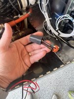
Finally came to a resolution on this issue. Here is what we eventually found. After pulling the seal off the back of the Gen A plug one of the wires was not seated properly. We definitely learned a lot about the electrical system in the process. Thanks for all the help and guidance
Tim
Tim
Attachments
Just when I was getting ready to contact you guys, you post this. Great news.Finally came to a resolution on this issue. Here is what we eventually found. After pulling the seal off the back of the Gen A plug one of the wires was not seated properly. We definitely learned a lot about the electrical system in the process. Thanks for all the help and guidance
Tim
Finally came to a resolution on this issue. Here is what we eventually found. After pulling the seal off the back of the Gen A plug one of the wires was not seated properly. We definitely learned a lot about the electrical system in the process. Thanks for all the help and guidance
Tim
Thanks for posting the resolution!
