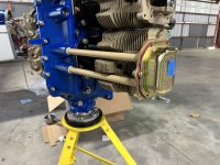
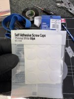
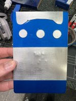
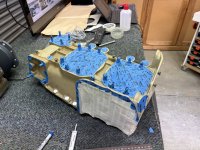
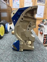
I have watched *all* of the engine overhaul videos I can find, and it seems that most people use little masking dots to mask off the areas on the case, and accessory case, where the hardware goes.
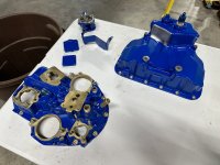
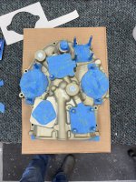
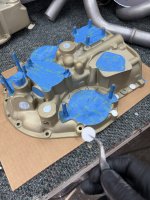
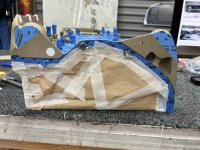
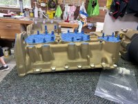
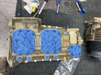
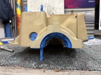
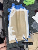
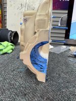
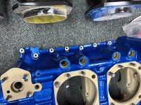
Here is an example of the accessory case from one video:

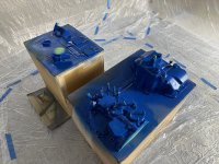
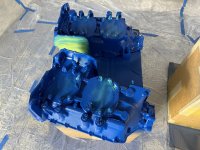
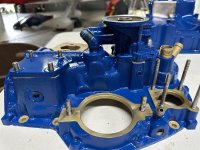
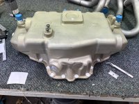
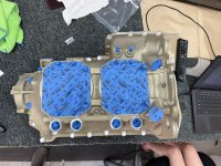
I am about to paint my engine and the shop told me they paint under these hardware locations on their engines.
The overhaul manual just says “Do not paint areas under hold down nuts where torque is required.”
So is the shop correct here? As the list of torques in the overhaul manual doesn’t include case mating bolts, accessory or sump mating bolts etc.
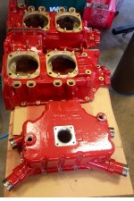
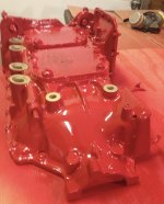
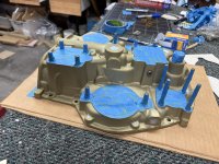
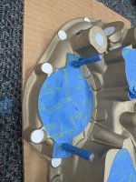
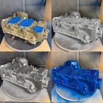
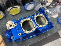
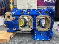
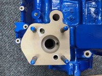
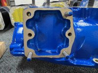
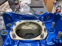
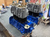
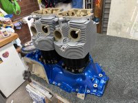
I found a good kitplanes article which shows the case painted under the case mating bolts. (And no masking in those spots in the before photos)


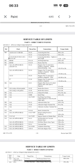
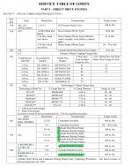
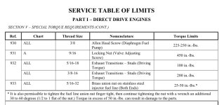
For completeness, attached below are the torque values from the overhaul manual. My engine is a S, or S6. No mention of any hardware on the case, except cylinder hold down nuts. So I am assuming paint under the aforementioned hardware is fine?
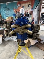
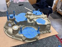
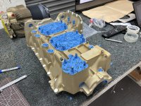
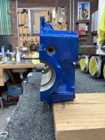
Here is an example of the accessory case from one video:
I am about to paint my engine and the shop told me they paint under these hardware locations on their engines.
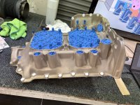
The overhaul manual just says “Do not paint areas under hold down nuts where torque is required.”
So is the shop correct here? As the list of torques in the overhaul manual doesn’t include case mating bolts, accessory or sump mating bolts etc.
I found a good kitplanes article which shows the case painted under the case mating bolts. (And no masking in those spots in the before photos)
For completeness, attached below are the torque values from the overhaul manual. My engine is a S, or S6. No mention of any hardware on the case, except cylinder hold down nuts. So I am assuming paint under the aforementioned hardware is fine?