Van's Air Force

The definitive Van's Aircraft support community! Buying, building or flying an RV? Join our exclusive family of mentors and enthusiasts!

Magnet on Plasma III magnet ring

Hello,

I am looking for alternate solution to replace the little magnets that the Lightspeed electronic ignition system uses underneath the flywheel on / in the timing ring as set timing. On the attached photo the magenta colored "dots" are the magnets. Any info would be appreciated. Thank you.
20251025_092133.jpg
Thank you.
 
Sounds like there might be a story here.

Try https://www.kjmagnetics.com/ for a replacement magnet. I've bought a number of magnets from there and they have a good selection and good service. Note that non-plastic-coated magnets are somewhat fragile. Also that if you drop any magnet it won't fall down, it'll fly off to stick on something magnet-colored.

Dave
 
Here we go again...

So you wanna go back to mags? So why change magnets? Throw what you certainly consider crap in the trash, and (re-)install the antediluvian mags, good luck.
Fun fact, looking at your picture of the ring doesn't really vouch for the careful install as required by this, and all other E-ignition systems.
 
Waaaay more to this story....
Yes, as indicated there is way more to the story. I was looking to source the magnets, not to vent. But if you'd like to know:

After a new system installation of PLASMA III, and quite a few months of fighting to refine the set up and to make it work I asked Klaus to sell me two new magnets as I would like to relocate the magnets to a more advanced position. He asked why and I answered because the timing is waaay retarded. He asked how I figure. I told him that after I installed his Plasma III my plane lost around 13 - 14 kts speed, and the CHT dropped from my normal 400 F to 340 F, so naturally one would just adjust the timing a tad. With the magnet ring and the fixed timing positions it is not that easy to just adjust the timing. Last weekend I relocated the magnets one position further in advance, but I had no chance yet to test fly it this way because of 70 kts wind over the weekend. I would like to have a couple magnets in my hand for more "adjustment if needed" because I am not sure if this one position will be enough to get my performance back that I had with a mag before, for which Klaus responded to put the mag back because he doesn't think advancing the timing will fix those things and also my speeds I showed him photos of are way out of normal so he doesn't believe those speeds are real.

[vendor bashing text deleted per VAF rules; S.Buchanan]
 
Last edited by a moderator:
Here we go again...

So you wanna go back to mags? So why change magnets? Throw what you certainly consider crap in the trash, and (re-)install the antediluvian mags, good luck.
Fun fact, looking at your picture of the ring doesn't really vouch for the careful install as required by this, and all other E-ignition systems.
Yes, Klaus!
 
The magnets you have in magenta above are located in the most-retarded position possible. Did you use an automotive timing light to verify timing as directed in the manual?

We might be able to help if you post photos of your installation, particularly of the sensor and how you mounted it.

Also, the rubbing on the perimeter of the ring indicates sensor spacing to ring is incorrect. That interference might also have ruined the sensor.
 
The magnets you have in magenta above are located in the most-retarded position possible...
I know, thank you for your input. That's my point to relocate them. I moved the magnets one position to more advance, but given my low CHT the one moved position might be not enough and it needs to be moved one more position. These magnets are fragile and I am worried that I might break one during the relocating process and I wanted to have one on hand so I can just use a new one if needed. I just marked them magenta so I know which way is their face when I reinstalled them later.

Also the source to the scratches had been fixed and anything else in that system works fine.

The attached photo shows the adjusted magnet ring timing, one position toward advance. I think I have to move it one more hole, but I wanted to do it in steps and test fly it between the steps.
 

Attachments

  • 20251025_153741.jpg
    20251025_153741.jpg
    472.7 KB · Views: 50
Last edited:
mmmh, not sure, but is the ring correctly positioned inside the flywheel? The location/drilling/taping of those is paramount. OTOH, by the symptoms you describe there's definitely something wrong in the timing, and moving those magnets (not magnetos 😉 
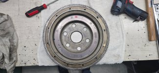
) might help. Determining how much off the present ones are would help installing new ones in the correct location.
 
When I asked to see a pic of the sensor installation, I wanted to know which side of the plate it's mounted on. If it's on the opposite side of the plate, that would retard timing significantly. And your loss of 13 kts indicates substantially retarded timing. Like way more than a few degrees. These engines are typically pretty insensitive to timing. Is your sensor mounted on the left side of the plate like this:

1761586198538.jpeg

Again, did you ever use a timing light to verify what you actually had?

You can get magnets here: https://www.mcmaster.com/products/magnets/magnets-2~/neodymium-magnets-7/
 
Again, did you ever use a timing light to verify what you actually had?
My pick up sensor wiring was approved by Klaus. I have two systems running on the timing magnet ring and both were placed correctly, and frankly both are running "just fine" except the performance loss and the low CHT temps.

I was going to use a timing light, but then I also thought from the onset that a timing light set up was a way too cumbersome undertaking and asked Klaus what else can be done, and he actually suggested me to build two connectors, connecting them into the OUTPUT of each of the PLASMA III red boxes and read out the timing that way. And I did. Despite the obvious retarded configuration results he said there is nothing wrong with my timing and I just have to live with the lower speed and the much lower CHT AND that I should block the cooling air inlet to get higher CHT.

[vendor bashing text deleted per VAF rules; S.Buchanan]
 

Attachments

  • 20250619_193834.jpg
    20250619_193834.jpg
    342.8 KB · Views: 31
  • 20250619_190006.jpg
    20250619_190006.jpg
    363.7 KB · Views: 31
  • 20250620_195754.jpg
    20250620_195754.jpg
    348 KB · Views: 31
Last edited by a moderator:
A couple of thoughts:
- Of all the EI systems, LightSpeed has, in my experience, more timing advance than the rest of the field. So your reported change, while it does indicated retarded timing, points to another issue besides how the base magnets are set up.
- Please let us know about how you have the pick up mounted (post #12).
- Never run a LightSpeed ignition without verifying timing with a light. The LEDs show what the box thinks, not necessarily reality. Put a light on the engine. This is simple but take some precautions for being so close to the back of the prop while the engine is running. If you don’t have light buy one, or find an engine guy that did his own tune ups back in the day.

Carl
The timing output value comes directly from the CDI circuit. It's not something that an algorithm "figures out". If the output says 25° it's 25°...
 
The timing output value comes directly from the CDI circuit. It's not something that an algorithm "figures out". If the output says 25° it's 25°...
Not true. The LightSpeed MAP sensor is known to fail. When it does timing goes to 40+ degrees BTDC regardless of RPM or MP but the circuit still thinks it is at 25 or whatever base timing is.

The problem found only with a timing light.

Considering the indications, the OP has timing with indications are that it is not set correctly. Check it with a timing light.

Carl
 
I did a custom ignition system and used hall effect sensors for the pick up. I used molybdenum magnets or something like that. These are best for Hall effect sensors. You can get them in various sizes at digikey. They have polarity, so need to be sure you install them in the correct orientation.

I installed my magnets in the 12 holes in the ring gear, but that only works if you have access to the software to manage how the cpu counts magnets.

You will definitely need to verify timing, as magnet strength will impact the rise time and therefore see the magnet earlier or later based on the strength delta.
 
- Never run a LightSpeed ignition without verifying timing with a light. The LEDs show what the box thinks, not necessarily reality. Put a light on the engine. This is simple but take some precautions for being so close to the back of the prop while the engine is running. If you don’t have light buy one, or find an engine guy that did his own tune ups back in the day.

Carl

The only way to verify the timing is with a timing light on the back of the flywheel. It’s a simple, safe process with the proper precautions, and a helping hand in the cockpit. Done it many times. The output from the box tells you that the timing is changing with MP but that can be anywhere on the flywheel. The placement of the timing ring is crucial. I prefer the Hall effect sensor that goes in the mag hole. Much easier to time and make adjustments.
 
The only way to verify the timing is with a timing light on the back of the flywheel. It’s a simple, safe process with the proper precautions, and a helping hand in the cockpit. Done it many times. The output from the box tells you that the timing is changing with MP but that can be anywhere on the flywheel. The placement of the timing ring is crucial. I prefer the Hall effect sensor that goes in the mag hole. Much easier to time and make adjustments.
But, the Hall Effect sensors in the mag holes have a history of failed seals, letting oil into the sensor. Check it each Condition Inspection.

Carl
 
But, the Hall Effect sensors in the mag holes have a history of failed seals, letting oil into the sensor. Check it each Condition Inspection.

Carl
Based on how many times this has been quoted, I must have the only one that has not failed in 20 years...
 
I wonder why thousands of Lightspeed installations work perfectly with exactly the same installation and magnets in the same hole.
You refuse to do do even the most basic check on your system (timing check) and rather call the vendor names.
Clearly, there is a problem with your timing but it may require more than placing a new magnet into a new hole.
Perhaps your ring installation was incorrectly drilled and the only way to verify that is by doing a check with a timing light.
Not wanting to do a timing light check is like saying, "I am not getting in the water until I can swim, I could drown you know"
In my experience with Lightspeed ignitions, it is almost always, if not always the installation (installer) that is causing issues.
I have talked to Klaus many times and while he can be a bit abrupt at times, if I was you , I would take his installation instructions seriously.
 
I prefer the Hall effect sensor that goes in the mag hole. Much easier to time and make adjustments.
I had one of those Hall Effect modules for a few months, but nothing than trouble and inconsistent results. Klaus recommended, after I kept contacting him almost daily with new problems regarding the hall effect system, he told me straight out just switch to the crank sensor, he had enough with "his own hall effect system". I had a crank sensor before, so my hall effect sensor was the second Plasma III system on the plane. The crank sensor system worked for almost 10 years flawlessly along a magneto. At the time I switched from hall to the second crank sensor Klaus said that I HAVE to relocate the magnets according to the manual, which I did, and that's where I lost all the performance and the CHT went down. That was a clear indication that the magnets have to go back at least one position to get more advance since nothing "else" showed any different problems. He clearly stated that I just have to live with the performance loss and that he does not recommend moving the magnets, nor he has any recommendations. I literally considering P-Mag, just so I don't need to deal with him anymore. Or a turbine system or something. Or go back to gliding or paragliding.

[vendor bashing text deleted per VAF rules; S.Buchanan]
 

Attachments

  • 20230421_130733.jpg
    20230421_130733.jpg
    1.1 MB · Views: 18
  • 20230421_174840.jpg
    20230421_174840.jpg
    1.5 MB · Views: 18
Last edited by a moderator:
I wonder why thousands of Lightspeed installations work perfectly with exactly the same installation and magnets in the same hole.
That's the perfect question, but you also have to ask why there are multiple holes for different magnet settings. Because no two engines are the same. On my first crank sensor installation Klaus actually installed the magnets himself in the perfect location (perfect hole, but it sounds weird) and that worked fine there for 10 years. I am not even sure why he pushed on to relocate the magnets when they worked there just fine for a long time when I installed the second crank sensor?

Also, when there is a problem (low CHT temps) with an obvious solution (advance the timing a degree), why try to find, or even recommend to look for, a different solution?
 
I had one of those Hall Effect modules for a few months, but nothing than trouble and inconsistent results. Klaus recommended, after I kept contacting him almost daily with new problems regarding the hall effect system, he told me straight out just switch to the crank sensor, he had enough with "his own hall effect system". I had a crank sensor before, so my hall effect sensor was the second Plasma III system on the plane. The crank sensor system worked for almost 10 years flawlessly along a magneto. At the time I switched from hall to the second crank sensor Klaus said that I HAVE to relocate the magnets according to the manual, which I did, and that's where I lost all the performance and the CHT went down. That was a clear indication that the magnets have to go back at least one position to get more advance since nothing "else" showed any different problems. He clearly stated that I just have to live with the performance loss and that he does not recommend moving the magnets, nor he has any recommendations. I literally considering P-Mag, just so I don't need to deal with him anymore. Or a turbine system or something. Or go back to gliding or paragliding. Or he could just retire and a normal person could take over his business and all would be good... there, who asked me to vent?
I don't see how you are going to start moving magnets around while being unwilling to cross checking timing. Great way to get in all sorts of troube there. Magnet placement is NOT as simple as just observing the crank angle where the sensor sees the magnet in a static state. You must understand rise time and/or fall time as well as where on the rise or fall it triggers, based upon how it is coded - can be set up either way. I have built custom EFII systems. You can use static as a basic setup step, but must adjust via timing light on a running engine.

You also need a way to lock the controller into a fixed advance state so that you can cross check with a light.
 
Last edited:
another question, at the time you ordered the system were the specification you gave on the order form correct (compression, timing requested)? As there been any change made to the engine?

said that I HAVE to relocate the magnets
and
he does not recommend moving the magnets
sound a bit contradictory to me...
 
We love to help solve problems but we also like to hear of problems solved.
Thank you for asking.
The weather and my schedule finally opened up and I went for a test flight today. Relocating the magnets and with that advancing the timing was exactly as expected. I should have moved the magnets two holes towards advance, not only one. I have a timing changing potmeter installed months ago and today I was able to reach 401F CHT and a few kts speed gain, after turning the potmeter a few degree towards advance. Before I relocated the magnets I wasn't able to change the timing enough to let the CHT climb higher than 340 F. The goal is again to have an optimal timing at mid timing-setting, so I don't have to operate the potmeter to achieve higher temps through more optimal burning. I will order a few magnets - thank you for sharing the source - and I will relocate the magnets one more position toward advance. Thank you everyone for the constructive criticism and for everyone's input. I also apologize for my negative tone here and there. I am new here and I should be more polite. I will do better.
 
Thanks for your update!

Two questions: are the two PLASMA III boxes interconnected as per the schematic? And assuming they are interconnected, does a single timing adjustment potentiometer then adjust timing on both boxes?
 
...are the two PLASMA III boxes interconnected as per the schematic?
No, they are not interconnected anymore. I have a double level potmeter, controlling both red boxes at the same time, but individually (separately). My two red boxes were interconnected at first, but I removed that connection later.
 

Attachments

  • Screenshot 2025-10-30 140109.png
    Screenshot 2025-10-30 140109.png
    493.2 KB · Views: 4
No, they are not interconnected anymore. I have a double level potmeter, controlling both red boxes at the same time, but individually (separately). My two red boxes were interconnected at first, but I removed that connection later.
If you are still looking for magnets try SDS they use the same magnet.
 
I have a timing changing potmeter installed months ago….
This!!!!!

If you mentioned in your original post about installing these pots we could have solved this problem after your first post. I did a field repair fixing five LightSpeed Plasma II+ boxes that the board pot connections had wrong resistors (100 ohm instead of 100K ohm or something like that, I don’t remember). Timing went way advanced regardless of pot settings.

But once again, a timing light on the engine after install, as required in the LightSpeed installation, would have found this!

I say again, do not fly after a LightSpeed ignition install without verifying timing with a light. This is simple to do. Do not trust the Lightspeed LEDs to reflect truth until you verify with a light.

Carl
 
Last edited:
Great to hear of your progress.
I am wondering why you are set on seeing CHTs in the 400F range?
While 400F is ok for a Lycoming it is a bit high in my book and a range that many of us try to stay below.
My CHTs are routinely running below 350F and I can keep up with any RV-10.
Also, what sort of speeds are you seeing in your RV ? and which RV do you own?
 
Back
Top