I’m looking at contactors for battery and starter. The Van’s supplied parts can be gotten from Digikey at lower prices (and free shipping!) than I can get from US based vendors.
I believe this is the master contactor which comes from Vans:
 www.digikey.com.au

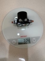
And this is the starter contactor:
www.digikey.com.au

This is described as:
“12v 500a grounded four stud solenoid with phenolic housing with ignition coil resistor shorting circuit”
The question:
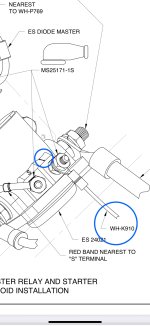
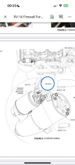
All of the AEC diagrams show power being sent to the start contactor by the start switch, then it grounds via the case.
Why?
Why don’t we use a contactor which gets power straight from the battery lead to the contactor, then close the contactor by grounding at the start button? (Same as we do with the master contactor or any other relay).
Seems in the same range there are many options to do it this way.
For instance - this one would get coil power from the battery lead (with a jumper) and just need a ground at the start switch (would need a fly back diode I think).
www.digikey.com.au

Also:
They make nice ones which are PVC coated:
I was thinking of using 3 of these - 2 for my battery Master relay’s, and 1 for the x-tie:
https://www.digikey.com.au/en/products/detail/littelfuse-commercial-vehicle-products/24117/6347078

I believe this is the master contactor which comes from Vans:
24115 | DigiKey Electronics
Order today, ships today. 24115 – General Purpose Relay SPST-NO (1 Form A) 12VDC Coil Chassis Mount from Cole Hersee. Pricing and Availability on millions of electronic components from Digi-Key Electronics.
And this is the starter contactor:
24021 | DigiKey Electronics
Order today, ships today. 24021 – General Purpose Relay SPST-NO (1 Form A) 12VDC Coil Chassis Mount from Cole Hersee. Pricing and Availability on millions of electronic components from Digi-Key Electronics.
This is described as:
“12v 500a grounded four stud solenoid with phenolic housing with ignition coil resistor shorting circuit”
The question:
All of the AEC diagrams show power being sent to the start contactor by the start switch, then it grounds via the case.
Why?
Why don’t we use a contactor which gets power straight from the battery lead to the contactor, then close the contactor by grounding at the start button? (Same as we do with the master contactor or any other relay).
Seems in the same range there are many options to do it this way.
For instance - this one would get coil power from the battery lead (with a jumper) and just need a ground at the start switch (would need a fly back diode I think).
24023 | DigiKey Electronics
Order today, ships today. 24023 – General Purpose Relay SPST-NO (1 Form A) 12VDC Coil Chassis Mount from Cole Hersee. Pricing and Availability on millions of electronic components from Digi-Key Electronics.
Also:
They make nice ones which are PVC coated:
I was thinking of using 3 of these - 2 for my battery Master relay’s, and 1 for the x-tie:
https://www.digikey.com.au/en/products/detail/littelfuse-commercial-vehicle-products/24117/6347078
Last edited: