
Van's Air Force
You are using an out of date browser. It may not display this or other websites correctly.
You should upgrade or use an alternative browser.
You should upgrade or use an alternative browser.
Replacing Lasar/Slick mags with E-mags - RPM wiring
- Thread starter William Johnston
- Start date

With the VM1000, you’ll need to change the emag output to 1 pulse per revolution rather than the standard 2 ppr. You’ll also want to install the diode included with your emag to reduce the tach output voltage to 5volts rather than the standard 12volts.
Emags output (send) rpm signals even when they’re “turned off” for a mag check, so only one of your emags needs to be modified as I described above. The diode is directional and just goesinline in the wire between pin 1 and pin 6 on the mag and your VM1000. To change the pulses per revolution, you’ll need to adjust the mag’s internal software settings using emagair’s EICAD software or the box produced by enginebridge.com I could never get the manfacturer’s software to work, so I used the Enginebridge box.
I just went through this when I converted my RV-3 to dual eMags. Happy to help in any way I can.
Emags output (send) rpm signals even when they’re “turned off” for a mag check, so only one of your emags needs to be modified as I described above. The diode is directional and just goes
I just went through this when I converted my RV-3 to dual eMags. Happy to help in any way I can.
Last edited:
William Johnston
I'm New Here
So I connect the green wire coming from the VM1000 with the diode and just cap off the red and black?With the VM1000, you’ll need to change the emag output to 1 pulse per revolution rather than the standard 2 ppr. You’ll also want to install the diode included with your emag to reduce the tach output voltage to 5volts rather than the standard 12volts.
Emags output (send) rpm signals even when they’re “turned off” for a mag check, so only one of your emags needs to be modified as I described above. The diode is directional and just goes inline in the wire between the mag and your VM1000. To change the pulses per revolution, you’ll need to adjust the mag’s internal software settings using emagair’s EICAD software or the box produced by enginebridge.com I could never get the manfacturer’s software to work, so I used the Enginebridge box.
I just went through this when I converted my RV-3 to dual eMags. Happy to help in any way I can.
Can I get your phone number to have my mechanic give you a call?With the VM1000, you’ll need to change the emag output to 1 pulse per revolution rather than the standard 2 ppr. You’ll also want to install the diode included with your emag to reduce the tach output voltage to 5volts rather than the standard 12volts.
Emags output (send) rpm signals even when they’re “turned off” for a mag check, so only one of your emags needs to be modified as I described above. The diode is directional and just goes inline in the wire between the mag and your VM1000. To change the pulses per revolution, you’ll need to adjust the mag’s internal software settings using emagair’s EICAD software or the box produced by enginebridge.com I could never get the manfacturer’s software to work, so I used the Enginebridge box.
I just went through this when I converted my RV-3 to dual eMags. Happy to help in any way I can.
Sent a PM with my phone number.So I connect the green wire coming from the VM1000 with the diode and just cap off the red and black?
Can I get your phone number to have my mechanic give you a call?
Also, for anybody else following this thread, I made a mistake in my original post… the diode to reduce the tach output voltage goes between ground (pin 1) and the tach output (pin 6). The diode directional band goes toward pin 6.
See page 17 of the eMag installation instructions dated 06-2025 for the wiring diagram.
That is not part of the LASAR System.Replacing my Lasar/Slick setup with E-Mags due to Lasar system going out. Does anyone know which of the 3 wires coming off the Lasar RPM sensor on the slick mag (red, green and black) is for the data? It will be going to the Vision Microsystems 1000 EIS.
It is an aftermarket transducer to pick up RPM based on the magnet rotating inside the mag.
The LASAR System has a wire coming out of the controller that can be used for RPM on most but it appears that the builder of your airplane used a transducer that may have been furnished by Vision Microsystems for use with their 1000 EIS.
UMA makes a similar sensor and something similar may have been used by Vision Microsystems.
My suggestion is to find the Vision Microsystems manual and see what it recommends for RPM when not using a mag. I know the eMag instruction manual should have a wiring diagram that works with many engine monitors.
cameronstrafford
I'm New Here
Hi! I am now working on this. Similar to original post, my Slick mag had 3 wires coming out of it going into pins J4-10,11,12 on the VM1000's DPU.
I understand and follow adding the diode between pin 1 & 6 on the E-mag to reduce it to 5V. Hopefully the EICAD software works.
My question is as follows - in the VM1000 manual, it says to "install a blocking diode in series with Cathode (bar) going to the ignition side". Did anyone who made the swap from Lasar/Slick Mags to E-Mags add a diode as such? I don't quite understand the instructions - it's not clear what direction the blocking diode is supposed to be oriented, or what 'cathode (bar)' refers to?
Thanks!
Sent a PM with my phone number.
Also, for anybody else following this thread, I made a mistake in my original post… the diode to reduce the tach output voltage goes between ground (pin 1) and the tach output (pin 6). The diode directional band goes toward pin 6.
See page 17 of the eMag installation instructions dated 06-2025 for the wiring diagram.
In my case, I went from having the tach pickup for my VM1000 coming from a Bendix mag to converting over to a PMag. I didn’t change anything beyond the suggested diode between pins 1 annd 6 at the pMag and the pulses per revolution at the PMag. I didn’t trace the mag wire back to the VM1000, so I don’t know if there was another diode installed somewhere inline by the original builder.
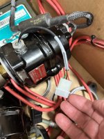
As to an explanation of the cathode side of a diaode, a picture is probably worth a thousand words.

As to an explanation of the cathode side of a diaode, a picture is probably worth a thousand words.
Hi! I am now working on this. Similar to original post, my Slick mag had 3 wires coming out of it going into pins J4-10,11,12 on the VM1000's DPU.
I understand and follow adding the diode between pin 1 & 6 on the E-mag to reduce it to 5V. Hopefully the EICAD software works.
My question is as follows - in the VM1000 manual, it says to "install a blocking diode in series with Cathode (bar) going to the ignition side". Did anyone who made the swap from Lasar/Slick Mags to E-Mags add a diode as such? I don't quite understand the instructions - it's not clear what direction the blocking diode is supposed to be oriented, or what 'cathode (bar)' refers to?
Thanks!
View attachment 108957
cameronstrafford
I'm New Here
Ah- I was much overthinking it, I didn't realize it was just instructions for installations.
While I am tempted with the "if it's not broke, don't mess with it", I can't imagine the diode will mess with anything. Will get it installed before the e mags go in. Thanks!!
While I am tempted with the "if it's not broke, don't mess with it", I can't imagine the diode will mess with anything. Will get it installed before the e mags go in. Thanks!!
