Hi,
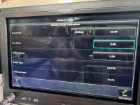
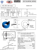
I am using an Amploc Key 100 hall effect sensor to read amps to/from the battery. According to the Amploc manual it should read around 2.2v with 0 amps passing through it. However, the G3X is showing a sensor value of just 0.075v at 0 amps.
I have the Key 100 wired as follows:
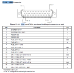
Inner (pin 1) goes to Pin 14 on J244 GP4 +5v
Center (pin 2) goes to Pin 16 on J244 GP4 Ground
Outer (pin 3) goes to pin 15 on J244 GP4 in
I have also tried wiring the sensor to pins 30, 31 and 32 (GP5) with the same results.
I have tested continuity from the J244 connector back to the connector for the sensor and all the pins all match with no crossover, shorts or noticeable resistance. I have confirmed that +5v and Ground are correctly reading at the hall effect sensor connector.
I have carefully removed pin 15 from the connector at the GEA end and, with the J244 reconnected to the GEA, confirmed there is 2.4v correctly reading at the crimp pin.
I have been through the G3X manual several times and can't see what I've done wrong. My thinking is that if pin 15 is reading 2.2v with a test meter at the J244 plug it should show the same on the G3X, right?
Steve at Amploc has been amazing, he sent a replacement unit but that does the same thing.
All other sensors I've wired such as flap, trim and fuel sensors work as expected.
Any suggestions on what I can test next or what I may have missed would be very much appreciated.
Thank you,
Abe
I am using an Amploc Key 100 hall effect sensor to read amps to/from the battery. According to the Amploc manual it should read around 2.2v with 0 amps passing through it. However, the G3X is showing a sensor value of just 0.075v at 0 amps.
I have the Key 100 wired as follows:
Inner (pin 1) goes to Pin 14 on J244 GP4 +5v
Center (pin 2) goes to Pin 16 on J244 GP4 Ground
Outer (pin 3) goes to pin 15 on J244 GP4 in
I have also tried wiring the sensor to pins 30, 31 and 32 (GP5) with the same results.
I have tested continuity from the J244 connector back to the connector for the sensor and all the pins all match with no crossover, shorts or noticeable resistance. I have confirmed that +5v and Ground are correctly reading at the hall effect sensor connector.
I have carefully removed pin 15 from the connector at the GEA end and, with the J244 reconnected to the GEA, confirmed there is 2.4v correctly reading at the crimp pin.
I have been through the G3X manual several times and can't see what I've done wrong. My thinking is that if pin 15 is reading 2.2v with a test meter at the J244 plug it should show the same on the G3X, right?
Steve at Amploc has been amazing, he sent a replacement unit but that does the same thing.
All other sensors I've wired such as flap, trim and fuel sensors work as expected.
Any suggestions on what I can test next or what I may have missed would be very much appreciated.
Thank you,
Abe