
Van's Air Force
You are using an out of date browser. It may not display this or other websites correctly.
You should upgrade or use an alternative browser.
You should upgrade or use an alternative browser.
RV-6A Very Slow Build, Western Australia
- Thread starter PaulvS
- Start date

More grins on the way
Thanks Dan, et al for PMs. What started out as 1 day job for SB 06-2-23 has blown out to be a much bigger job. I need to remind myself that one day this will all be worth it.
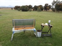
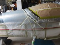
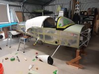
I made some more progress cleaning out the softened Proseal, using a spray gun with solvent and a stiff brush, supporting the tank on its nose in a stand. I moved everything outside in the yard to reduce the fumes and fire hazard.
It's become more evident that much of the sealant in the faying surface joints between the stiffeners, ribs and skins has also softened and reverted to goo. I tentatively removed the pop rivets between the baffle and flanges on an internal rib and was able to push a feeler gauge through the soft Proseal. I think therefore that the tanks need to come apart completely (approx 4-500 rivets to drill out!) for total cleaning and then re-assembly. This is because I'm not confident about the long term performance of new sealant over the old sealant that is still in the seams, in case it contaminates the new sealant.
For the record, my work log shows that it took 5 months to build the tanks in 1995.
** Edit/update
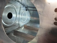
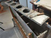
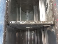
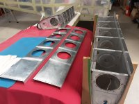
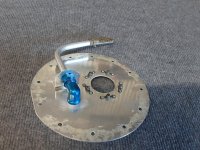
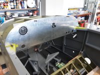
Added picture after removing tank baffle. Definitely needed to come off for repair, the Proseal underneath is a soft mess. Next step is to de-rivet and disassemble the tank ribs and stiffeners.
Thanks Dan, et al for PMs. What started out as 1 day job for SB 06-2-23 has blown out to be a much bigger job. I need to remind myself that one day this will all be worth it.
I made some more progress cleaning out the softened Proseal, using a spray gun with solvent and a stiff brush, supporting the tank on its nose in a stand. I moved everything outside in the yard to reduce the fumes and fire hazard.
It's become more evident that much of the sealant in the faying surface joints between the stiffeners, ribs and skins has also softened and reverted to goo. I tentatively removed the pop rivets between the baffle and flanges on an internal rib and was able to push a feeler gauge through the soft Proseal. I think therefore that the tanks need to come apart completely (approx 4-500 rivets to drill out!) for total cleaning and then re-assembly. This is because I'm not confident about the long term performance of new sealant over the old sealant that is still in the seams, in case it contaminates the new sealant.
For the record, my work log shows that it took 5 months to build the tanks in 1995.
** Edit/update
Added picture after removing tank baffle. Definitely needed to come off for repair, the Proseal underneath is a soft mess. Next step is to de-rivet and disassemble the tank ribs and stiffeners.
Attachments
Last edited:
Clean tanks
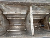
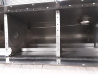
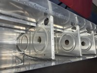
Both tanks are finally cleaned out, following removal of the aft baffles.
I now believe it won't be necessary to completely disassemble all of the ribs and stiffeners, because I've been able to wash out all of the Proseal goo using several litres of solvent. The most effective solvents were gun wash and acrylic enamel reducer, both have a high percentage of toluene. Acetone was partially effective and several other solvents that I tried did not work at all. I took the job outside due to the fumes and risk of fire.
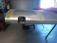
The still hardened Proseal on the outside of the tank that was not affected by the avgas vapor was very difficult to remove and the only thing that would take it off was paint stripper containing methylene chloride. It took 4 or 5 applications and lots of scraping with a wooden stick to remove the sealant.
I can't say this has been the most fun period on the project but at least the worst part of cleaning is done. Thankfully a couple of buddies have helped me to hang on to my sanity during some dark moments!
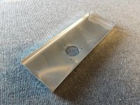
The sealant that I ordered has arrived and I've got the .040 aluminum sheet to make the access covers. I will certainly not be putting any fuel into the tanks for leak testing this time round!
Both tanks are finally cleaned out, following removal of the aft baffles.
I now believe it won't be necessary to completely disassemble all of the ribs and stiffeners, because I've been able to wash out all of the Proseal goo using several litres of solvent. The most effective solvents were gun wash and acrylic enamel reducer, both have a high percentage of toluene. Acetone was partially effective and several other solvents that I tried did not work at all. I took the job outside due to the fumes and risk of fire.
The still hardened Proseal on the outside of the tank that was not affected by the avgas vapor was very difficult to remove and the only thing that would take it off was paint stripper containing methylene chloride. It took 4 or 5 applications and lots of scraping with a wooden stick to remove the sealant.
I can't say this has been the most fun period on the project but at least the worst part of cleaning is done. Thankfully a couple of buddies have helped me to hang on to my sanity during some dark moments!
The sealant that I ordered has arrived and I've got the .040 aluminum sheet to make the access covers. I will certainly not be putting any fuel into the tanks for leak testing this time round!
Attachments
Last edited:
Zero4Zulu
Well Known Member
My tanks had slosh loose. I initially thought I could clean them myself. I removed the rear panel which wasn’t really difficult. After getting started and realizing how much chemical exposure I would have to endure, I started looking for options. I found a chemical stripping company locally. They dipped my tanks and they came out nice.
I re-applied Proseal around all the ribs and rivets and re-install the rear panels. So far a few years since then, no leaks. For others needing to do this, maybe you can locate a chemical stripping outfit near you. Of course you would have to repaint the tanks too.
I re-applied Proseal around all the ribs and rivets and re-install the rear panels. So far a few years since then, no leaks. For others needing to do this, maybe you can locate a chemical stripping outfit near you. Of course you would have to repaint the tanks too.
Last edited:
Wing lighting
The tanks are fully cleaned and ready for re-sealing and while waiting for the rest of the sealant to ship I worked on the wing lighting.
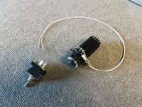
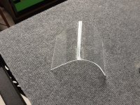
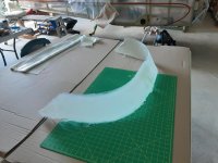
There will be one Flyleds Single Spotlight in the leading edge of each wing, powered by an integrated wig-wag toggle switch on the panel. I fabricated aluminum brackets to mount the lights in the wings and made the curved plexi lenses using the tank leading edge as a form.
The lights are compact and weigh about 100g each and the hole in the leading edge is 2.5" square, which is adequate for the narrow beam.
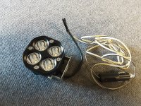
Another lighting option that I considered was eBay Baja style 4000 (claimed) lumen spotlights, however these are heavier and more difficult to mount and seem to produce not much more light than the Flyleds 1200 lumen lights. As an added bonus, Flyleds are made down under, so there was no international shipping!
This lighting solution is for day VFR, using the wig-wag function to enhance awareness.
The tanks are fully cleaned and ready for re-sealing and while waiting for the rest of the sealant to ship I worked on the wing lighting.
There will be one Flyleds Single Spotlight in the leading edge of each wing, powered by an integrated wig-wag toggle switch on the panel. I fabricated aluminum brackets to mount the lights in the wings and made the curved plexi lenses using the tank leading edge as a form.
The lights are compact and weigh about 100g each and the hole in the leading edge is 2.5" square, which is adequate for the narrow beam.
Another lighting option that I considered was eBay Baja style 4000 (claimed) lumen spotlights, however these are heavier and more difficult to mount and seem to produce not much more light than the Flyleds 1200 lumen lights. As an added bonus, Flyleds are made down under, so there was no international shipping!
This lighting solution is for day VFR, using the wig-wag function to enhance awareness.
Attachments
Flyleds are made down under, so there was no international shipping
Plus Paul offers first class service with top quality products
")
I upgraded my old halogen light with a combo leading edge landing / taxi, and I'm very happy.
Good work on those tanks, nice to follow your progress

Re-sealing the tanks
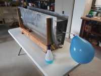
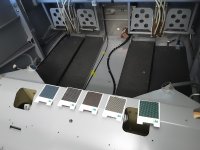
Both tanks have finally been internally re-sealed, after cleaning out all of the old failed sealant, which I really never want to do again. I applied polysulfide CS3204 B2 to all of the internal seams in the tank. The final step this week will be to re-install the rear baffles.
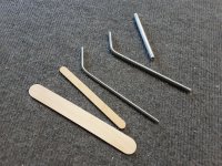
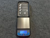
The re-sealing process that I followed was to force new sealant into all of the internal seams in the tanks. This was a little different to initial assembly, since the faying surfaces were already riveted. I trialled several tools for applying the sealant and the most effective was a length of bent rod, similar to what my old dentist used when making amalgum fillings. That 's a spin-off benefit from seeing the dentist! The small jewellers scale is graduated in 0.1g increments, which makes it easy to mix small batches when working slowly.
The smell of polysulfide sealant is unique and I'd forgotten all about it, however the memory came back instantly after 20 years.
I also fitted the Vans anti-rotation bracket on the fuel pickup tubes, this was actually the reason for opening the tanks several months ago, which then led to the whole unexpected repair job detour.
Scott McDaniels fuel tank construction videos on Youtube have been very helpful indeed.
Both tanks have finally been internally re-sealed, after cleaning out all of the old failed sealant, which I really never want to do again. I applied polysulfide CS3204 B2 to all of the internal seams in the tank. The final step this week will be to re-install the rear baffles.
The re-sealing process that I followed was to force new sealant into all of the internal seams in the tanks. This was a little different to initial assembly, since the faying surfaces were already riveted. I trialled several tools for applying the sealant and the most effective was a length of bent rod, similar to what my old dentist used when making amalgum fillings. That 's a spin-off benefit from seeing the dentist! The small jewellers scale is graduated in 0.1g increments, which makes it easy to mix small batches when working slowly.
The smell of polysulfide sealant is unique and I'd forgotten all about it, however the memory came back instantly after 20 years.
I also fitted the Vans anti-rotation bracket on the fuel pickup tubes, this was actually the reason for opening the tanks several months ago, which then led to the whole unexpected repair job detour.
Scott McDaniels fuel tank construction videos on Youtube have been very helpful indeed.
Attachments
Tanks fixed
I haven't updated here in a while but there has been steady progress, this is has definitely been a marathon and not a sprint.
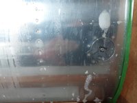
The tanks passed the leak test and the only bubbles were from the fuel caps between the strips of packing tape. Overall the tank repairs set me back about 2 months.
Then there was some home maintenance that needed to be done and that also took a couple of months. By then it was winter and too cold to resume work on the canopy.
I haven't updated here in a while but there has been steady progress, this is has definitely been a marathon and not a sprint.
The tanks passed the leak test and the only bubbles were from the fuel caps between the strips of packing tape. Overall the tank repairs set me back about 2 months.
Then there was some home maintenance that needed to be done and that also took a couple of months. By then it was winter and too cold to resume work on the canopy.
Attachments
Last edited:
Panel work
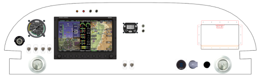
I wanted to keep the panel relatively simple, in keeping with the RV original concept, but now modernised. I fly day VFR only and most flying is local flights and that doesn't need an extensive panel.
I learned to fly in aircraft with analogue instruments and when I started flying our club RV-9A I referred only to those gauges and completely ignored the D100 EFIS that was also in the panel.
My low-n-slow Aeroprakt Foxbat forced me to use digital instrumentation because the panel has only a Dynon D180 EFIS, Garmin 296 GPS and a radio head. It is minimal, but fully functional.
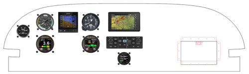
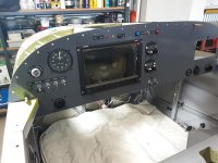
The panel concept for the RV-6A went through several iterations and I did the initial layout with the online panel designer, then scale drawing in CAD, and finally cardboard cutout mock-up in the cockpit.
The steam ASI is a backup in case everything else fails, and for old times comfort.
There is a map box in the panel also, I got that recent kit from Ralph Inkster on VAF. It is the only punched part on the plane.
I wanted to keep the panel relatively simple, in keeping with the RV original concept, but now modernised. I fly day VFR only and most flying is local flights and that doesn't need an extensive panel.
I learned to fly in aircraft with analogue instruments and when I started flying our club RV-9A I referred only to those gauges and completely ignored the D100 EFIS that was also in the panel.
My low-n-slow Aeroprakt Foxbat forced me to use digital instrumentation because the panel has only a Dynon D180 EFIS, Garmin 296 GPS and a radio head. It is minimal, but fully functional.
The panel concept for the RV-6A went through several iterations and I did the initial layout with the online panel designer, then scale drawing in CAD, and finally cardboard cutout mock-up in the cockpit.
The steam ASI is a backup in case everything else fails, and for old times comfort.
There is a map box in the panel also, I got that recent kit from Ralph Inkster on VAF. It is the only punched part on the plane.
Attachments
Last edited:
Seat cushions
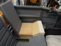
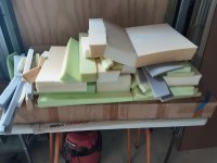
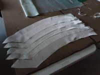
We are having a go at making our own seat cushions. My wife knows how to sew, mainly clothing though, so this is a bit of an experiment.
The white memory foam is cut from an Ikea mattress topper and all the shaping has been done using an electric carving knife. There were a few iterations to get the base thickness right and also the density for the back and it know feels quite comfortable.
I flame tested some fabric samples from the upholstery shop and they burned readily and continuously so plan B is to use rated 100% wool fabric. Still deciding on colors and whether to pick something conservative or a bit livelier.
Attachments
Last edited:
Canopy part II
I resumed working on the canopy, it had been packed away for winter (too cold in shop for plexi work).
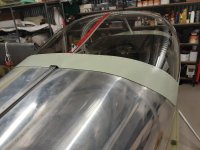
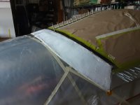
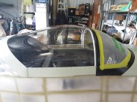
The side skirts worked out OK in metal, per the plans, but it didn't look to promising to use metal for the rear skirts because the canopy frame is too high at the centre, which would cause a gap. And I already had more than enough frustration with the canopy frame to not want to fight with metal anymore.
I used fibreglass and epoxy instead and moulded it directly on the fuselage with the canopy closed. The gap between the skin and the plexi was bridged with some tough plastic sheet for moulding over. The aft skirt is attached with rivets and I moulded in the locations by placing temporary marker rivets in the plexi holes.
There is still a small amount of sanding and filling to do when I paint it.
Next job on the list is the windscreen and I need to figure out if the skirt will be metal or fibreglass or a combo and maybe moulded directly onto the plexi or perhaps to be popped
off and finished off the plane and then re-attach.
I resumed working on the canopy, it had been packed away for winter (too cold in shop for plexi work).
The side skirts worked out OK in metal, per the plans, but it didn't look to promising to use metal for the rear skirts because the canopy frame is too high at the centre, which would cause a gap. And I already had more than enough frustration with the canopy frame to not want to fight with metal anymore.
I used fibreglass and epoxy instead and moulded it directly on the fuselage with the canopy closed. The gap between the skin and the plexi was bridged with some tough plastic sheet for moulding over. The aft skirt is attached with rivets and I moulded in the locations by placing temporary marker rivets in the plexi holes.
There is still a small amount of sanding and filling to do when I paint it.
Next job on the list is the windscreen and I need to figure out if the skirt will be metal or fibreglass or a combo and maybe moulded directly onto the plexi or perhaps to be popped
off and finished off the plane and then re-attach.
Attachments
Last edited:
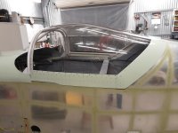
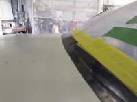
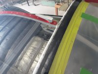
Windscreen complete
Hi Dan, we'll see if mine seals OK in flight! There are some historical posts on VAF about how to seal if there is a gap and somebody posted success by using a piece of soft vinyl adhesive strip that is loose on one edge, kind of like the baffle seals in the engine bay. The air pressure pushes the vinyl against the fuselage skin to make an effective seal.
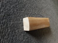
I've completed the windscreen and did it the traditional way per the plans using screws and fiberglass and epoxy for all of the fairings. It was very time consuming between waiting overnight for epoxy to cure and then subsequent sanding and filling. The epoxy is tinted black so that the underside that is visible from the inside is inconspicuous. Most of the sanding was done with a small 1.5" wide wooden block that has one face shaped to a 4" radius. I didn't want to use a full round 4 or 5 inch pipe due to the risk of inadvertently scratching the plexi.
If I was too do anything different "next time" (i.e. never!) I would lay up the fairing foundation with a couple of 1.5 strips of very fine bias or crow foot fabric. I found it a bit awkward following the plan recommendations to start with a narrow strip of fabric and then put on progressively wider strips of fabric. The final widest strip of fabric is intended to butt up against the electrical tape border and that is a bit tricky do a neat job with the 6 oz or 9 oz cloth.
The windscreen was initially glued in at the sides on the inside face with Fixtech FS200 adhesive (similar to Silpruf) to hold it in place while being glassed in. The glareshield was painted black before attaching the windscreen.
Th next task on the list is the empennage fairing.
Nice work on that skirt Paul.
Mine were made using aluminum, and don’t fit the contour as closely as yours… the resultant being water getting sucked in when flying thru wet atmospheric conditions. I’m still working on the most suitable seal.
Hi Dan, we'll see if mine seals OK in flight! There are some historical posts on VAF about how to seal if there is a gap and somebody posted success by using a piece of soft vinyl adhesive strip that is loose on one edge, kind of like the baffle seals in the engine bay. The air pressure pushes the vinyl against the fuselage skin to make an effective seal.
I've completed the windscreen and did it the traditional way per the plans using screws and fiberglass and epoxy for all of the fairings. It was very time consuming between waiting overnight for epoxy to cure and then subsequent sanding and filling. The epoxy is tinted black so that the underside that is visible from the inside is inconspicuous. Most of the sanding was done with a small 1.5" wide wooden block that has one face shaped to a 4" radius. I didn't want to use a full round 4 or 5 inch pipe due to the risk of inadvertently scratching the plexi.
If I was too do anything different "next time" (i.e. never!) I would lay up the fairing foundation with a couple of 1.5 strips of very fine bias or crow foot fabric. I found it a bit awkward following the plan recommendations to start with a narrow strip of fabric and then put on progressively wider strips of fabric. The final widest strip of fabric is intended to butt up against the electrical tape border and that is a bit tricky do a neat job with the 6 oz or 9 oz cloth.
The windscreen was initially glued in at the sides on the inside face with Fixtech FS200 adhesive (similar to Silpruf) to hold it in place while being glassed in. The glareshield was painted black before attaching the windscreen.
Th next task on the list is the empennage fairing.
Attachments
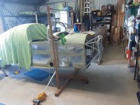
Pants on 380x150-5
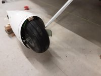
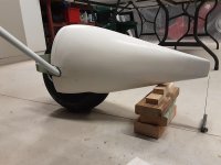
The empennage fairing is done and I'm now working on fitting the wheel pants to the oversize 380x150-5 tires. It's easier to do this now before the engine is mounted, since that would make the fuselage heavier to lift off the ground.
There's a fair bit of trimming and fiddling to get the pants aligned and mounted onto the brackets. It looks like a significant gap greater than 1/4" between the inner brackets (U-810) and the fiberglass so that will need either fiberglass buildup or modifications to the brackets.
The wheel pants are going to fit OK over the bigger tires. I've made the top clearance spacer block 3/4" instead of 1" and the centre line of the pants is 9.25" above the floor instead of 8 5/8".
It's Xmas Eve here, so festive greetings to everyone who is celebrating!
Attachments
The wheel pants have been fitted and the intersection fairings were also made while it was easy to lift the fuselage and align everything in the flying position. I'll make another post with photos of the details. I'm glad to be doing something other than fiberglass next. I don't mind the process too much other than it is very time consuming.
Today I got ready to start working on the engine installation. The shop has been rearranged for better access to the fwd end and I shifted the engine from the store room to the workshop. This is a mid-time O-320 that has been rebuilt a while ago and I need to refresh the fuel pump, carburetor and magnetos.


Today I got ready to start working on the engine installation. The shop has been rearranged for better access to the fwd end and I shifted the engine from the store room to the workshop. This is a mid-time O-320 that has been rebuilt a while ago and I need to refresh the fuel pump, carburetor and magnetos.
I haven't posted an update in a while so here goes...
In summary, a year has passed and the end is finally in sight. I am currently painting the airframe, prior to final assembly, and most of it is done and "only" the fuselage is still to be painted.
The FWF work was challenging but interesting. The most time consuming part was fitting the baffle kit and each quarter took 3 or 4 days to fit to the engine.
The FWF plans for the RV-6A leave most of the details to the builder, so I used the RV-7A plans as a guide. I deviated from the plans in a couple of areas, i.e. the oil cooler is located on the firewall instead of the baffle behind #4 cylinder. The plenum is moulded from epoxy glass around a drink bottle that is the correct diameter.


I also changed the ram air induction for the FAB to use a piece of SCAT to connect the removable nose piece. This makes it easier to take off and refiit the bottom cowl and should also give a good seal between the inlet and the FAB.

I also changed the ram air induction for the FAB to use a piece of SCAT to connect the removable nose piece. This makes it easier to take off and refiit the bottom cowl and should also give a good seal between the inlet and the FAB.
I've been building for almost 32 years now, today February 25th 2025 is almost the anniversary of when I started, on March 17th 1993. There was a break of about 14 years when I did not make any progress because of other things in life that became more important.
This morning was a milestone, spraying the final coat of paint on the fuselage. I've been painting the components individually, before final assembly. It takes typically three days to cycle parts through the temporary paint booth, day 1 is cleaning and prep followed by epoxy primer, which cures overnight. Day 2 is wet sanding and scuffing the primer for top coat with single stage 2K industrial polyurethane. Day 3 is taking out the cured painted parts and cleaning out the booth.
The paint booth is framed from steel tube and wood, which is covered in plastic tarpaulins and sealed with duct tape.
Steel brackets for tube to slide into

Tube frame is supported by the brackets


Covered over with large tarpaulin and taped. The booth is 20' x 12' x 8' high.

Extraction fan with the yellow duct was too small, replaced with bigger duct and fan that is much more effective at clearing out the overspray.


This morning was a milestone, spraying the final coat of paint on the fuselage. I've been painting the components individually, before final assembly. It takes typically three days to cycle parts through the temporary paint booth, day 1 is cleaning and prep followed by epoxy primer, which cures overnight. Day 2 is wet sanding and scuffing the primer for top coat with single stage 2K industrial polyurethane. Day 3 is taking out the cured painted parts and cleaning out the booth.
The paint booth is framed from steel tube and wood, which is covered in plastic tarpaulins and sealed with duct tape.
Steel brackets for tube to slide into
Tube frame is supported by the brackets
Covered over with large tarpaulin and taped. The booth is 20' x 12' x 8' high.
Extraction fan with the yellow duct was too small, replaced with bigger duct and fan that is much more effective at clearing out the overspray.
Last edited:
The paint scheme is a bit retro, since this is a legacy model, I also like the paint scheme on 1957 Corvette. The two tone scheme on the fuselage is to make it easier for me to paint by breaking it into two jobs instead of trying to do the whole thing at once.


.jpeg")
The rudder is checkered/chequered, this took some time to lay out and mask with fineline tape.


White squares were painted over the red background

The rudder is checkered/chequered, this took some time to lay out and mask with fineline tape.
White squares were painted over the red background
The wings are mostly white. I painted the first wing vertically and got runs that needed to be sanded off and then re-shot.


I painted the second wing flat and rotated it over during the spraying session.

The fiberglass tips are red and the outboard end of the wing is red also; the curve follows a paper template and is masked with plastic fineline tape.


I painted the second wing flat and rotated it over during the spraying session.
The fiberglass tips are red and the outboard end of the wing is red also; the curve follows a paper template and is masked with plastic fineline tape.
Last edited:
The canopy was a challenge to support and hanging from overhead worked out OK. Masking both sides was time consuming.


I also suspended the HS for spraying. Much of the challege in painting the RV has been the 3 dimensional parts, compared to painting a car that is more like 2D.

The tanks were painted off the wing, supported on bars.

I also suspended the HS for spraying. Much of the challege in painting the RV has been the 3 dimensional parts, compared to painting a car that is more like 2D.
The tanks were painted off the wing, supported on bars.
Finally, the fuselage is being painted, I left the hardest item until the end, hoping to develop some skills on the simpler parts before tackling this big item.
Lifted onto car ramps for better access underneath. The grey green is the 2K epoxy primer.

The belly and the sides were sprayed white, in separate sessions. I masked the belly while the sides were being painted.

Sides and belly and cabin masked caretully before the red topcoat. The masking took a good half day to apply.


Lifted onto car ramps for better access underneath. The grey green is the 2K epoxy primer.
The belly and the sides were sprayed white, in separate sessions. I masked the belly while the sides were being painted.
Sides and belly and cabin masked caretully before the red topcoat. The masking took a good half day to apply.
Last edited:
Temperature was just right this morning, 22 degrees C and relative humidity 55%. I got the paint mixed and filled the cup and had a problem with the gun leaking. First time that this ever happened!


This wouldn't be an RV project if there wasn't a challenge and a problem to solve! Gun has been emptied and cleaned (small piece of debris had dislodged and obstructed nozzle) and continued on with spraying the top and sides.

Once the paint had hardened sufficiently, I could pull off the masking tape and paper. It's poppin, I'm kinda happy! Gotta like red...


Edit update: somebody pointed out the windscreen shouldn't be red, so that has been fixed and I agree it is better:

This wouldn't be an RV project if there wasn't a challenge and a problem to solve! Gun has been emptied and cleaned (small piece of debris had dislodged and obstructed nozzle) and continued on with spraying the top and sides.
Once the paint had hardened sufficiently, I could pull off the masking tape and paper. It's poppin, I'm kinda happy! Gotta like red...
Edit update: somebody pointed out the windscreen shouldn't be red, so that has been fixed and I agree it is better:
Last edited:
Compliments for your work Paul... and tenacity ")
This will be one beautifully crafted bird. And the good thing is that despite having been superseded by the -7 (which in turn is being superseded by the -14 (for those who can afford it...)), the -6 still offers fantastic handling and performance.
Nice to see you making good progress, and thanks for the reports.
PS
Had a laugh reading your comments on baffling since I'm exactly at this phase in the process of my new engine installation...
Awesome looking work Paul. Next time I need my 6A painted, it’s headed your way! Of course, there’s the small matter of the ferry flight from San Jose California to Western Australia, but I’ll figure that one out!Temperature was just right this morning, 22 degrees C and relative humidity 55%. I got the paint mixed and filled the cup and had a problem with the gun leaking. First time that this ever happened!
View attachment 81644
View attachment 81642
This wouldn't be an RV project if there wasn't a challenge and a problem to solve! Gun has been emptied and cleaned (small piece of debris had dislodged and obstructed nozzle) and continued on with spraying the top and sides.
View attachment 81643
Once the paint had hardened sufficiently, I could pull off the masking tape and paper. It's poppin, I'm kinda happy! Gotta like red...
View attachment 81645View attachment 81646
Last edited:
YOU CAN DO IT!!!! Hey bought an RV-7 slow build, all kits in 2004.... First few years made progress. Job changes it went into storage, two moves. 19 yrs later... working on it full time... Wings almost done, already started on fuselage. Having helped building a non pre-punch RV-6, looking at your work, you are doing great. Keep going!!!!
21 yrs and counting, About to register, and may be 2026 will have a plane...
21 yrs and counting, About to register, and may be 2026 will have a plane...
Recent life events intervened and so I needed to put the RV project aside for a bit while recovering from some storm damage.
It has not really rained here since October 2025 and all of a sudden there was 120mm, which is 25% of the annual rainfall.
It caused erosion and debris was washed all over, including 10T of dirt onto the airstrip. Fortunately the buildings and inhabitants were all OK and most of the important cleanup is done, so RV work can resume.
All of the external painting is essentially complete now but when I went to fit the cowls there was a noticeable mismatch between the paint finish and the rest of the fuselage. There was more orange peel on the cowls than I liked and this is probably because they were painted quite early on, before I had some more practice and experience from painting the rest of the airframe. The cowls would probably be passable but since the paint booth was still set up I sanded back the cowls and re-sprayed them. This added two days to the project, which doesn't seem like much on top of 32 years.
I'm now finishing off details in the engine bay and cockpit before moving the fuselage out to the hangar and putting on the wings.
Pics of the cowls after re-painting:


I'm now finishing off details in the engine bay and cockpit before moving the fuselage out to the hangar and putting on the wings.
Pics of the cowls after re-painting:
Last edited:
Paul, I noticed in an old photo that this service bulletin was not completed.... https://www.vansaircraft.com/service-information-and-revisions/sb-99-06-1/
The paint job looks great!! Not many have the guts to paint their RV.
The paint job looks great!! Not many have the guts to paint their RV.
Attachments
Thanks Warren, you have sharp eyes, and another pair is always welcome! The SB was done some time later after Vans sent the finger patches and a local TIG welder put them on the pedals.Paul, I noticed in an old photo that this service bulletin was not completed.... https://www.vansaircraft.com/service-information-and-revisions/sb-99-06-1/
The paint job looks great!! Not many have the guts to paint their RV.
I can now appreciate why some builders get a pro to paint their RV, but part of the incentive to try DIY is that shops like Evoke give a starting price guide of over $30K.
The cowl, and the rest of the paint job look awesome. Love the color. Could be Porsche Guards Red.All of the external painting is essentially complete now but when I went to fit the cowls there was a noticeable mismatch between the paint finish and the rest of the fuselage. There was more orange peel on the cowls than I liked and this is probably because they were painted quite early on, before I had some more practice and experience from painting the rest of the airframe. The cowls would probably be passable but since the paint booth was still set up I sanded back the cowls and re-sprayed them. This added two days to the project, which doesn't seem like much on top of 32 years.
I'm now finishing off details in the engine bay and cockpit before moving the fuselage out to the hangar and putting on the wings.
Pics of the cowls after re-painting:
View attachment 83851
View attachment 83852
View attachment 83853
Still on the path to moving the completed parts into the hangar for final assembly and first engine run etc. I hit a bit of a snag. The plan was to put the RV into the hangar with the Foxbat and on a scale drawing it looked like both aircraft would fit into the 12m x 10.5m space. In practice it's not however going to be very easy to manoevre everything into position without risking hangar rash.
Hangar with Foxbat:

In order to make enough space to fit more comfortably I am enlarging the hangar and making a 3m deep extension "Tee" at the back to house the tail section of either plane. Today's job is to pour the concrete floor and the RV should be able to move in within a couple of weeks.


Just in case you are wondering why I am mixing concrete on site instead of ordering the readymix truck... well it is a long way out to the farm from the depot for a small load, and I need the exercise.
Hangar with Foxbat:
In order to make enough space to fit more comfortably I am enlarging the hangar and making a 3m deep extension "Tee" at the back to house the tail section of either plane. Today's job is to pour the concrete floor and the RV should be able to move in within a couple of weeks.
Just in case you are wondering why I am mixing concrete on site instead of ordering the readymix truck... well it is a long way out to the farm from the depot for a small load, and I need the exercise.
Don't you love these little side projects? Spice in life
Now what you're doing (able to do) is unconceivable in a certain mini country paralysed in the middle of Europe... Having sooo much space, having one's own field, runway, hangar... though I realise there are downsides to everything, this kind of stuff has me dreaming aloud.
Looking forward to your next instalments.
PS
Though I could now have opened a thread about my own running project... would be titled "the long story of a slide down the rat's hole - replacing your engine rapidly. Not".
A bit more progress... by now it's nearly the middle of May. I extended the hangar by making a Tee in the back wall in order to fit the RV and then wheeled it over from the workshop. It looks so small in there without the wings on, behind the mighty Foxbat (normal TAS 75 knots).

The engine crane is lifting the fuselage just enough to take the weight off the main gear and remove the wing main spar temporary stub.

My teenage son helped me to put the left wing on and it was as expected, i.e. a bit of a battle to slide in the spar and align the holes for the pins.


The next step is to fit the right wing and then the splice plates and the close tolerance and other bolts.
A couple of buddies came over to the farm strip in our club RV-9A to check on my progress, and that helped with motivation!

The engine crane is lifting the fuselage just enough to take the weight off the main gear and remove the wing main spar temporary stub.
My teenage son helped me to put the left wing on and it was as expected, i.e. a bit of a battle to slide in the spar and align the holes for the pins.
The next step is to fit the right wing and then the splice plates and the close tolerance and other bolts.
A couple of buddies came over to the farm strip in our club RV-9A to check on my progress, and that helped with motivation!
Last edited:
Hey Paul,A bit more progress... by now it's nearly the middle of May. I extended the hangar by making a Tee in the back wall in order to fit the RV and then wheeled it over from the workshop. It looks so small in there without the wings on, behind the mighty Foxbat (normal TAS 75 knots).
View attachment 87306
The engine crane is lifting the fuselage just enough to take the weight off the main gear and remove the wing main spar temporary stub.
View attachment 87308
My teenage son helped me to put the left wing on and it was as expected, i.e. a bit of a battle to slide in the spar and align the holes for the pins.
View attachment 87307
View attachment 87309
The next step is to fit the right wing and then the splice plates and the close tolerance and other bolts.
A couple of buddies came over to the farm strip in our club RV-9A to check on my progress, and that helped with motivation!
View attachment 87310
Looks good.
I installed my wings after lifting the fuselage and building a cradle under the carry through spar (similar to the one it sat on during the top side fuselage construction). Might have been a bit easier to slide the first wing in with it resting on the cradle….don’t know for sure. In any case, the close tolerance splice plate bolts (installed first) were “challenging”, but ultimately doable with use of liquid Boelube and “gentle” taps with a zero rebound mallet and wooden block. Then there are all the other standard bolts on the same spar, including the ones through the gear mount……
 . Sigh! It’s a process, enjoy the ride.
I hope to never ever need to take the wings off again. .. it was a real "bear" to fit the centre splice plates and close tolerance bolts. There were no short cuts and the most essential tool was a hammer. The close tolerance bolts have been in the wing spars previously when I pinned the parts together for riveting a long time ago.

Another quite time consuming task was installing the (inaccessible) bolts and nuts that attach the main gear leg brackets.
It looks more like an aeroplane now and I'm motivated to fit the tanks and hook up the controls and plumbing.


.. it was a real "bear" to fit the centre splice plates and close tolerance bolts. There were no short cuts and the most essential tool was a hammer. The close tolerance bolts have been in the wing spars previously when I pinned the parts together for riveting a long time ago.Another quite time consuming task was installing the (inaccessible) bolts and nuts that attach the main gear leg brackets.
It looks more like an aeroplane now and I'm motivated to fit the tanks and hook up the controls and plumbing.
I'm continuing on with the remaining "1% work" final assembly and have so far fitted the wing fuel tanks and connected their lines, as well as the ailerons, the Flyleds wig-wag landing lights and the wing tips. The control columns and main pushrods have been installed and the elevators are mounted on the horizontal stabilizer.
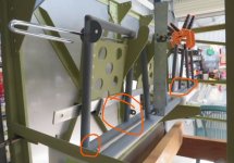
I hit a couple of snags today when trying to fit the rudder. There was interference between the bolts that attach the vertical stabilizer and the fairing on the bottom of the rudder. The AN4 bolts are installed per the plans with the heads facing forwards but they will need to turned around to prevent the tails from contacting the rudder and preventing full travel.

Another issue is that the rudder rod ends did not align with the hinge brackets on the vertical stabilizer and unfortunately it's not a matter of adjusting the rod ends to correct the problem. The issue is that the mounting plate between the vertical stabilizer and HS spar needs to be replaced and re-drilled to bring the VS hinge brackets into perfect alignment. Something must have shifted or been clamped incorrectly when I previously drilled the holes for the attaching plate, and so the bolt holes are out by 3/32".


This has all been a bit slow going and frustrating to be honest, partly because there is limited space for access to see and fit the bolts and washers and nuts etc. So I've just been working away at it and taking "breaks" to do some outside yard work in the fresh air and enjoy the peace.

I hit a couple of snags today when trying to fit the rudder. There was interference between the bolts that attach the vertical stabilizer and the fairing on the bottom of the rudder. The AN4 bolts are installed per the plans with the heads facing forwards but they will need to turned around to prevent the tails from contacting the rudder and preventing full travel.
Another issue is that the rudder rod ends did not align with the hinge brackets on the vertical stabilizer and unfortunately it's not a matter of adjusting the rod ends to correct the problem. The issue is that the mounting plate between the vertical stabilizer and HS spar needs to be replaced and re-drilled to bring the VS hinge brackets into perfect alignment. Something must have shifted or been clamped incorrectly when I previously drilled the holes for the attaching plate, and so the bolt holes are out by 3/32".
This has all been a bit slow going and frustrating to be honest, partly because there is limited space for access to see and fit the bolts and washers and nuts etc. So I've just been working away at it and taking "breaks" to do some outside yard work in the fresh air and enjoy the peace.
Absolutely Paulenjoy the peace
What a great picture... and mindset, which I sure should apply to myself more, just ask my wife (not...).
Ok, I'll think about it later (...), as for now, and specifically you, plough ahead, I really hope you'll be rewarded to the fullest with that labor of love, sure close to the goal

Are those hinge brackets shifted horizontally? Left/right?I'm continuing on with the remaining "1% work" final assembly and have so far fitted the wing fuel tanks and connected their lines, as well as the ailerons, the Flyleds wig-wag landing lights and the wing tips. The control columns and main pushrods have been installed and the elevators are mounted on the horizontal stabilizer.
I hit a couple of snags today when trying to fit the rudder. There was interference between the bolts that attach the vertical stabilizer and the fairing on the bottom of the rudder. The AN4 bolts are installed per the plans with the heads facing forwards but they will need to turned around to prevent the tails from contacting the rudder and preventing full travel.
View attachment 89756
Another issue is that the rudder rod ends did not align with the hinge brackets on the vertical stabilizer and unfortunately it's not a matter of adjusting the rod ends to correct the problem. The issue is that the mounting plate between the vertical stabilizer and HS spar needs to be replaced and re-drilled to bring the VS hinge brackets into perfect alignment. Something must have shifted or been clamped incorrectly when I previously drilled the holes for the attaching plate, and so the bolt holes are out by 3/32".
View attachment 89757
View attachment 89758
This has all been a bit slow going and frustrating to be honest, partly because there is limited space for access to see and fit the bolts and washers and nuts etc. So I've just been working away at it and taking "breaks" to do some outside yard work in the fresh air and enjoy the peace.
View attachment 89759
The hinge brackets are in the correct position horizontally, i.e. they are aligned with the centre line of the VS spar channel. The mis-alignment in the fore-aft direction is a result of a slight bit of flex in the VS spar when I drilled the mounting plate that attaches the fwd spar of the VS to the HS. This put the centre hinge bracket out of alignment by about 1/32" in the fore-aft direction. If the 4 bolts are removed and the VS is flexed back very slightly then the brackets can be perfectly aligned.Are those hinge brackets shifted horizontally? Left/right?
Thanks Dan, I really thought it would be finished by now and it appeared there would be only a couple of weeks work to re-assemble everything after painting, haha. There was the bit of extra work to extend the hangar and since then the RV assembly work has been slow going because of limited access e.g. to reach and adjust rod ends and get the little washers in there. Umpteen have slipped out and dropped down to be fished out with a magnet. If I try to rush, it just ends up taking longer!Absolutely Paul
What a great picture... and mindset, which I sure should apply to myself more, just ask my wife (not...).
Ok, I'll think about it later (...), as for now, and specifically you, plough ahead, I really hope you'll be rewarded to the fullest with that labor of love, sure close to the goal
I may be missing something but this fore amd aft misalignment can't be adjusted by moving the heim joints in and out by screwing or unscrewing them a bit? Now I'm just curious I guess.The hinge brackets are in the correct position horizontally, i.e. they are aligned with the centre line of the VS spar channel. The mis-alignment in the fore-aft direction is a result of a slight bit of flex in the VS spar when I drilled the mounting plate that attaches the fwd spar of the VS to the HS. This put the centre hinge bracket out of alignment by about 1/32" in the fore-aft direction. If the 4 bolts are removed and the VS is flexed back very slightly then the brackets can be perfectly aligned.
If the hinge brackets on the spar are mis-aligned due to the spar being "bowed", then compensating by adjusting the heim joints on the rudder will result in those hinge points being mis-aligned "bowed" also. I have been using a string line stretched through the centre points of the heim joints, and then separately also the rudder brackets, to check that they are in a perfectly straight line. Then, when the rudder is fitted to the VS the bolts should slide in without any difficulty, because all of the hinge points are aligned about the same axis.I may be missing something but this fore amd aft misalignment can't be adjusted by moving the heim joints in and out by screwing or unscrewing them a bit? Now I'm just curious I guess.
Spar being "bowed", AH, that was not in my mental equation. That is an issue.If the hinge brackets on the spar are mis-aligned due to the spar being "bowed", then compensating by adjusting the heim joints on the rudder will result in those hinge points being mis-aligned "bowed" also. I have been using a string line stretched through the centre points of the heim joints, and then separately also the rudder brackets, to check that they are in a perfectly straight line. Then, when the rudder is fitted to the VS the bolts should slide in without any difficulty, because all of the hinge points are aligned about the same axis.
Today I'm down in the detail of fitting the ailerons and flaps to the wings and have encountered some interference between the aileron pushrod and the flap skin leading edge. There is no mention of this issue on the plans, but it seems inevitable.

Interference location at the corner of the flap skin, marked with black sharpie:

After a few rounds of trimming and sanding the surfaces can now move without rubbing:

It's surprising how many bits and pieces have been needed for final assembly:

Interference location at the corner of the flap skin, marked with black sharpie:
After a few rounds of trimming and sanding the surfaces can now move without rubbing:
It's surprising how many bits and pieces have been needed for final assembly:
Last edited:
The interference you've noted above is normal. My machine is the same - as are all the ones I've seen around the country. I found this issue early on during a trial assembly, before the aircraft was painted (thankfully). The modification you've made is appropriate but maybe just smooth it off and make it look less obvious. I trimmed mine to have a taper that extends about 1.5" down the flap edge so it can't catch on the wing skin.
Looks like its really coming together now. Exciting! Can't wait to see your name plastered across the "First Flights" section of Vans's website.
Looks like its really coming together now. Exciting! Can't wait to see your name plastered across the "First Flights" section of Vans's website.
Last edited:
This post was going to be about the seat cushions but that update will be another day because today was a bit more interesting. There was a break in the weather (been raining all week) so it was fine enough to go outside and put some fire in the holes. The last time this engine ran was 32 years ago at overhaul and since then it has been stored indoors and preserved with LPS3 in the jugs. I washed out the cylinders with kerosene to clean out the waxy residue and checked the fuel system for flow rate and leaks (I picked up a drum of avgas at the airport yesterday). The carburetor has been overhauled as well as the 2 Bendix magnetos and along with the new fuel and oil lines, ignition harness, throttle and mixture cable etc. it was a bit surprising that the dang thing started and ran OK!

My wife was standing by with the fire extinguisher and video and there was just a bit of smoke out of the exhaust at the start and otherwise no leaks or any obvious problems. Some of the EMS gauge ranges will need to be adjusted.

I taxied around to check steering and brakes and there is a bit of "judder" from the brake pads, probably because they are not yet broken in.

My wife was standing by with the fire extinguisher and video and there was just a bit of smoke out of the exhaust at the start and otherwise no leaks or any obvious problems. Some of the EMS gauge ranges will need to be adjusted.
I taxied around to check steering and brakes and there is a bit of "judder" from the brake pads, probably because they are not yet broken in.
Last edited:
