rcarsey
Well Known Member
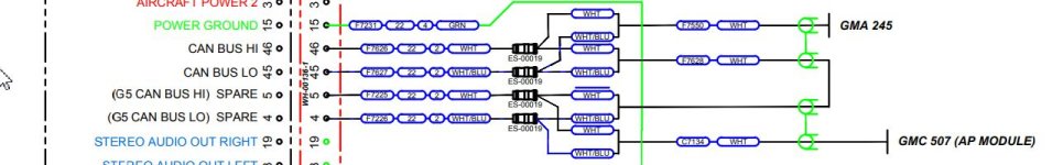
So the latest RV-12iS/Garmin wiring diagram from Vans has a couple extra CAN bus pins going to the MFD screen's connector that are labeled "G5". The engineers parked the pins on the MFD in positions that aren't used for the G3X.. So they're there to easily extend the CAN bus to a G5. Along with that, the EFIS power circuit (7.5A) is using about 3A in real life, so the extra 250mA for a G5 isn't a big deal...
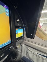
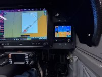
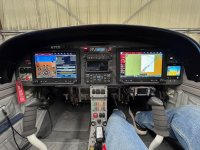
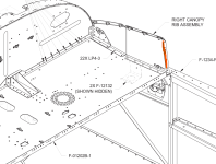
So after spending 3 hours of thinking, planning, cutting, and filing down a 3" hole for the G5.. I realized that that there is interference from the aluminum bar which supports the plexiglass canopy (the same bar that caused many G3X builders to file down the corners of the G3x and/or the bar itself). However, given the near-bezel-less design of the G5, there isn't anything to file down.. and the interference (at least where I positioned it) is too great to cut into the aluminum bar.
Has anyone gotten the G5 to fit in this location? I think the only (and actually the easiest option.. the one I probably should have started with) is to recess-mount the G5. I'm not thrilled on how it will look, but it seems the only way to avoid cutting into some things that I don't really want to cut into..