

The pilot in this story achieved perhaps a best-possible outcome, but the aircraft owner, builder, and maintainer chose poorly, to say the least. They are all one and the same person--namely me. Comes now the penitent, seeking the solace of public confession in the Chapel of VAF.
On Saturday, March 15, 2025, I was forced to land in a cow pasture 3.5 nautical miles NW of the Byron, CA airport (C83) after my RV-9A’s IO-320 engine suddenly lost all power. There were no signs of any trouble during three previous flights that same day.
No one was hurt, most importantly my Young Eagle passenger, taking his very first flight in a light aircraft. Except for cracked and shattered wheel pants the airframe was undamaged. More could be said about the in-flight actions and decisions I took and all that…but for the Safety forum I’ll focus on the cause.
The NTSB quickly ruled the event was an incident: I could move N748PK to its home base at nearby Livermore airport (LVK). However, the Oakland FSDO requested the plane to be otherwise left alone: They would come out to inspect it (and its logbooks) in-person. Mutual availability ultimately aligned two weeks later, March 29, 2025.
In the interim, I downloaded the engine data from 8PK’s Dynon EFIS, which showed all 4 cylinders went cold at precisely the same time, coinciding with fuel flow dropping from 6-7 gph (normal for LOP operations) to 1 gph. Indicated fuel pressure remained at 27-30 psi until the prop stopped windmilling just before touch-down.
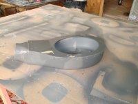
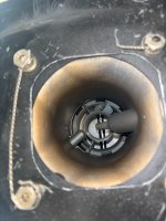
On the appointed day two (count ‘em—two!) ASI’s arrived at my hangar. I had already taken off the top cowling, but from the topside nothing was out of sorts. As I knelt to remove the lower cowl I looked into the snout of the air intake for the first time since pre-flighting the airplane the morning of the 15th.
Zoinks! There it was, big as life. A rubber flap (baffle seal material, actually), curled up against the air filter in the FAB, covering about 80% of the snout’s inlet area.
“Hey guys, you’ll want to shine your flashlights in here and take a picture. Pretty sure this is why the engine lost power. And it’s on me, 100%, and twice on Sunday.”
Now how in the world did a baffle seal find its way into the FAB?
During the last condition inspection (August 2024, tach hours 191.9) I noticed the K&N filter had started fretting the bottom of the FAB. Not deep enough to break through a generous epoxy layer exposing any fibers, but it was clearly going to do so sooner or later. This VAF thread discusses the issue. A common solution is firmly bonding a metal plate to the bottom of the FAB for the air filter to bear on.
But the elliptical hole in the FAB top was too small to pass a rigid plate that was larger than the filter. (The odds of making and positioning a plate the exact size and shape of the as-installed filter were rather slim, I thought). Besides, it would be such a PITA, cleaning out the oily-fuelish ooze that coats the FAB’s innards, then thoroughly roughening the smooth epoxy for good bonding.
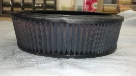
And then I had my not-so brilliant idea: cut an "O"- shaped rubber “gasket” from leftover baffle sheet. So easily passed into the FAB to sit between the bottom edge of the filter and the bottom of the FAB, the extra “squeeze” on the filter would immobilize its vibration and stop the fretting. What could possibly go wrong?
Looking into the snout to check that no critters or other foreign matter have taken up residence is, I swear, a faithfully performed part of every pre-flight. In 40 hrs and 26 flights since the last CI, the gasket material was always visible, peeking out past the bottom of the filter, exactly where I had put it. Surely it could never move?
Alas, it did move. [And don't call me Shirley.] The rubber gasket had slipped forward, allowing it to flip up in the incoming air flow. I honestly thought it couldn’t move. [Well, what did you expect—remember that slippery, oily-fuelish ooze that accumulates in the FAB?] I couldn’t have been more wrong. Or more humbled.
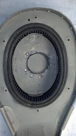
After taking off the bottom cowl, I opened the FAB alternate air door and found that the back half of the "O", which of course slipped forward too, had been sucked up against the mouth of the fuel servo throttle body, blocking about 90% of its intake area. I hadn’t gotten to opening the alternate air door before committing to land—we were less than 2000 AGL when the power went out. Evidently it wouldn’t have changed the outcome anyway.
The blocked airflow also explained the drop in fuel flow. The injection servo sends fuel up to the spider in proportion to mass airflow through the intake. But with the airflow so severely restricted, the air-fuel mixture, if any, that did reach the cylinders was evidently incombustible. I thus have the dubious distinction of taking out not just one, but two sides of the combustion trinity! Now that takes…talent?
I am so very aware how much of a lucky so-and-so I am. When that ill-conceived gasket slipped I didn’t run out of altitude, airspeed, and ideas all at the same time. It could have happened down low, just after take-off, and turned out so much worse.
The moral of the story: Any contemplated changes, my fellow Experimenters, especially ones related to fuel and airflow systems, deserve serious second and third thoughts. Preferably, by second and third brains in the heads of others. [A sentiment the FSDO ASIs expressed quite forcibly.] It may be highly unlikely anyone in the VAF community could possibly pull a boneheaded move like mine. But if this bit of public flagellation prompts even one aviator/builder to think twice, seek constructive feedback, and avoid a misadventure like mine, I gladly offer up this egregious example of what not to do.


On Saturday, March 15, 2025, I was forced to land in a cow pasture 3.5 nautical miles NW of the Byron, CA airport (C83) after my RV-9A’s IO-320 engine suddenly lost all power. There were no signs of any trouble during three previous flights that same day.
No one was hurt, most importantly my Young Eagle passenger, taking his very first flight in a light aircraft.
Except for cracked and shattered wheel pants the airframe was undamaged. More could be said about the in-flight actions and decisions I took and all that…but for the Safety forum I’ll focus on the cause.The NTSB quickly ruled the event was an incident: I could move N748PK to its home base at nearby Livermore airport (LVK). However, the Oakland FSDO requested the plane to be otherwise left alone: They would come out to inspect it (and its logbooks) in-person. Mutual availability ultimately aligned two weeks later, March 29, 2025.
In the interim, I downloaded the engine data from 8PK’s Dynon EFIS, which showed all 4 cylinders went cold at precisely the same time, coinciding with fuel flow dropping from 6-7 gph (normal for LOP operations) to 1 gph. Indicated fuel pressure remained at 27-30 psi until the prop stopped windmilling just before touch-down.
On the appointed day two (count ‘em—two!) ASI’s arrived at my hangar. I had already taken off the top cowling, but from the topside nothing was out of sorts. As I knelt to remove the lower cowl I looked into the snout of the air intake for the first time since pre-flighting the airplane the morning of the 15th.
Zoinks! There it was, big as life. A rubber flap (baffle seal material, actually), curled up against the air filter in the FAB, covering about 80% of the snout’s inlet area.
“Hey guys, you’ll want to shine your flashlights in here and take a picture. Pretty sure this is why the engine lost power. And it’s on me, 100%, and twice on Sunday.”
Now how in the world did a baffle seal find its way into the FAB?
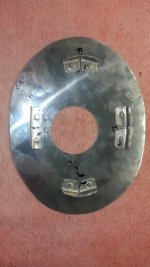
During the last condition inspection (August 2024, tach hours 191.9) I noticed the K&N filter had started fretting the bottom of the FAB. Not deep enough to break through a generous epoxy layer exposing any fibers, but it was clearly going to do so sooner or later. This VAF thread discusses the issue. A common solution is firmly bonding a metal plate to the bottom of the FAB for the air filter to bear on.
But the elliptical hole in the FAB top was too small to pass a rigid plate that was larger than the filter. (The odds of making and positioning a plate the exact size and shape of the as-installed filter were rather slim, I thought). Besides, it would be such a PITA, cleaning out the oily-fuelish ooze that coats the FAB’s innards, then thoroughly roughening the smooth epoxy for good bonding.
And then I had my not-so brilliant idea: cut an "O"- shaped rubber “gasket” from leftover baffle sheet. So easily passed into the FAB to sit between the bottom edge of the filter and the bottom of the FAB, the extra “squeeze” on the filter would immobilize its vibration and stop the fretting. What could possibly go wrong?
Looking into the snout to check that no critters or other foreign matter have taken up residence is, I swear, a faithfully performed part of every pre-flight. In 40 hrs and 26 flights since the last CI, the gasket material was always visible, peeking out past the bottom of the filter, exactly where I had put it. Surely it could never move?
Alas, it did move. [And don't call me Shirley.] The rubber gasket had slipped forward, allowing it to flip up in the incoming air flow. I honestly thought it couldn’t move. [Well, what did you expect—remember that slippery, oily-fuelish ooze that accumulates in the FAB?] I couldn’t have been more wrong. Or more humbled.
After taking off the bottom cowl, I opened the FAB alternate air door and found that the back half of the "O", which of course slipped forward too, had been sucked up against the mouth of the fuel servo throttle body, blocking about 90% of its intake area. I hadn’t gotten to opening the alternate air door before committing to land—we were less than 2000 AGL when the power went out. Evidently it wouldn’t have changed the outcome anyway.
The blocked airflow also explained the drop in fuel flow. The injection servo sends fuel up to the spider in proportion to mass airflow through the intake. But with the airflow so severely restricted, the air-fuel mixture, if any, that did reach the cylinders was evidently incombustible. I thus have the dubious distinction of taking out not just one, but two sides of the combustion trinity! Now that takes…talent?
I am so very aware how much of a lucky so-and-so I am. When that ill-conceived gasket slipped I didn’t run out of altitude, airspeed, and ideas all at the same time. It could have happened down low, just after take-off, and turned out so much worse.
The moral of the story: Any contemplated changes, my fellow Experimenters, especially ones related to fuel and airflow systems, deserve serious second and third thoughts. Preferably, by second and third brains in the heads of others. [A sentiment the FSDO ASIs expressed quite forcibly.] It may be highly unlikely anyone in the VAF community could possibly pull a boneheaded move like mine. But if this bit of public flagellation prompts even one aviator/builder to think twice, seek constructive feedback, and avoid a misadventure like mine, I gladly offer up this egregious example of what not to do.


 I actually feel pretty good about this "solution", although still admit there is some risk. Seems like it's a question of weighing the risks of ingesting something into the engine versus not ingesting any air. I fly IFR quite a bit, and flying through rain and snow are not unusual. We also have a ton of birds in my area.


.jpg")

