Hi,
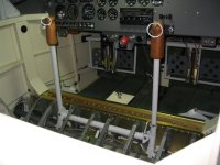
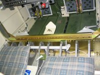
I'm slowly plodding along on finishing one of those '90%' complete RV-6A builds. Tonight I was looking at doing some work measuring up brackets to add a 5 point seatbelt harness, but I started looking at the seat ribs themselves and started to question everything.
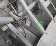
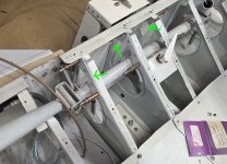
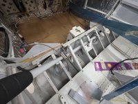
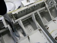
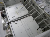
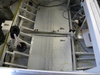
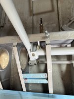
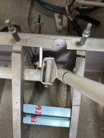
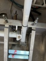
At first I noticed that they were kinked like someone had manhandled them trying to wedge something into place. This really didn't give me the warmest of fuzzies. But then on closer inspection it looks like the ribs have been cut away and mended.
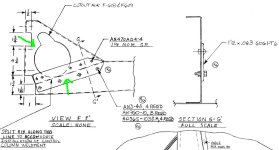
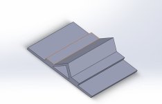
I checked the plans and from what I can tell the ribs are supposed to be cut to fit the control column in there, but not in this manner. View F F' on drawing 33 shows the cut is supposed to be cut which starts from where the rear flat section is and goes towards the hole... this is not that. It does seem kind of patched like the ribs on an RV7 but there is no missing flange. On this one the flange is missing and the web is cut completely away. From the other RV6 builds I've seen none of them are done this way, so it's got me questioning if this is correct.
So 2 questions:
1. Are the kinks in the rib concerning / warrant replacement or reinforcement?
2. Has anyone seen this kind of cutting before (i.e. is it a common mod?)
3. Can anyone share some pictures of their seat rib section here? The one's I've been able to find are a bit small and blurry.
In parallel I'm sending an email off to Vans, will report back with what they say.
Thanks!
I'm slowly plodding along on finishing one of those '90%' complete RV-6A builds. Tonight I was looking at doing some work measuring up brackets to add a 5 point seatbelt harness, but I started looking at the seat ribs themselves and started to question everything.
At first I noticed that they were kinked like someone had manhandled them trying to wedge something into place. This really didn't give me the warmest of fuzzies. But then on closer inspection it looks like the ribs have been cut away and mended.
I checked the plans and from what I can tell the ribs are supposed to be cut to fit the control column in there, but not in this manner. View F F' on drawing 33 shows the cut is supposed to be cut which starts from where the rear flat section is and goes towards the hole... this is not that. It does seem kind of patched like the ribs on an RV7 but there is no missing flange. On this one the flange is missing and the web is cut completely away. From the other RV6 builds I've seen none of them are done this way, so it's got me questioning if this is correct.
So 2 questions:
1. Are the kinks in the rib concerning / warrant replacement or reinforcement?
2. Has anyone seen this kind of cutting before (i.e. is it a common mod?)
3. Can anyone share some pictures of their seat rib section here? The one's I've been able to find are a bit small and blurry.
In parallel I'm sending an email off to Vans, will report back with what they say.
Thanks!