What is the critical dimension on the elevator alignment? Is it having the rod ends exactly 13/16 high, or having the counterweight arm exactly parallel with the lateral HS edge? I think that is is the counterweight arm, with the rode ends 13/16 min to a max 7/8 per the drawing. Does that sound right?

Van's Air Force
You are using an out of date browser. It may not display this or other websites correctly.
You should upgrade or use an alternative browser.
You should upgrade or use an alternative browser.
Elevator Alignment
- Thread starter JDA_BTR
- Start date

I clamped the elevator to the H stab and set the rod ends to the plans dimension initially. I had to make adjustments to the rod ends to bring the stick back to a more comfortable position for me when in the seat. Still have all rod ends in safety and get full travel but don't have to reach when in cruise.
Sorry. I misunderstood what you were asking. When I set the elevator rod ends to the drawing dimension the counterweight arms were parallel to the H stab and the elevator horns ended up parallel. No adjustment was required. Depending on how far off you are I would keep the rod ends the same and the horns parallel and if required trim the skins on the tabs or the H stab as required.
I had to lengthen the left elevator outboard rod end one full counterclockwise turn to make the left counterweight arm parallel to the H stab. Eyeballing a center mark on the middle bearing it seems to remain centered, and prior to the change it shifted ever so slightly. I'm not sure if anyone else ever had it this way. The right elevator is perfectly aligned with the rod end centers both at 13/16 per plans. I think that there must be some adjustment tolerance anticipated because the plans give a spec of 13/16 but a max of 7/8.
Yes, those rod ends are adjustable for a reason. The dimension Van's gives you should be pretty close and provides a good starting point. I'd shoot for the elevator counterweight arms being parallel to the HS skin. It sounds like that's what you've done.
Ideally, you'd be able to pull a tight string right down the middle of all those mounting hinge holes, but that's in a perfect world.
Ideally, you'd be able to pull a tight string right down the middle of all those mounting hinge holes, but that's in a perfect world.
I'm not an expert here. But, it seemed to me that the further away from the nominal hinge point dimension you are, the more you're going to have to fiddle with the elevator hinge stop to achieve full upward travel, and the less edge distance you're likely to end up with on the bolt hole for the elevator pitch horns. It seemed to me like this made a big difference when I was putting mine together. And, if the hinge bolts aren't in alignment (regardless of #turns in or out for any single one of them), there's going to be binding.
The spec for the rod end is 13/16. There is a max of 7/8. The initial question has become was is it best to line up the rod ends at the same height or adjust one a turn to make the counterweight arm exactly parallel to the HS side skin.
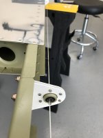
The holes at the center bearing aren’t drilled yet. I’m thinking it thru before doing it. Once drilled it becomes what it is!
I’m likely overthinking and just need to keep the arm aligned and go for it.
The holes at the center bearing aren’t drilled yet. I’m thinking it thru before doing it. Once drilled it becomes what it is!
I’m likely overthinking and just need to keep the arm aligned and go for it.
I like you, agonized over that alignment. The alignment of the elevator rotation axis is probably more important than anything else. It’s really a kinematic nightmare to align the lines between the hinge points, the center bearing and the 4 rod ends. The line through my HS hinges was not perfectly straight nor do I think it’s possible with the construction tolerances the kit uses. Plus that due to the nature of the rod ends the minimum adjustment you can make is limited to a half turn of the rod end thread .025” IIRC.
What I decided to do was go ahead and get a decent match of the skins keeping the rod end measurement as close as I could and drilled the arm to the center bearing. Then I put it together with the inboard hinge bolt without a nut and moved the elevator over its range of travel and checked to see if there was binding by verifying the bolt would still slide back and fourth in hinge/rod ends. if it didn’t I would move the rod end half a turn to see if I could minimize it. I think I might have moved one. In the end it seems to work and fly wonderfully.
What I decided to do was go ahead and get a decent match of the skins keeping the rod end measurement as close as I could and drilled the arm to the center bearing. Then I put it together with the inboard hinge bolt without a nut and moved the elevator over its range of travel and checked to see if there was binding by verifying the bolt would still slide back and fourth in hinge/rod ends. if it didn’t I would move the rod end half a turn to see if I could minimize it. I think I might have moved one. In the end it seems to work and fly wonderfully.
Attachments
Last edited:
I had to make adjustments to the rod ends to bring the stick back to a more comfortable position for me when in the seat. Still have all rod ends in safety and get full travel but don't have to reach when in cruise.
Off topic, but on the side-by-sides, a builder can get into trouble when trying to rig the stick for a more upright neutral position. The geometry of the parts is such that the yoke binds against the rod end with full aft stick. It puts a cyclical bending force on the threaded elevator pushrod end, a very bad thing.
The plans show the stick leaned forward at neutral for a reason.
We now return you to your regular programming....

My 7 was fine adjusted as per the plans. My 8 not so much. Had to reach too far to be comfortable at neutral. I adjusted it back to be in a comfortable position ensuring no binding with full travel at both ends and all rod ends in safety. Feels fine in flight now. I was referring to my 8 in my post...I know my handle is misleading but I don't think I can change it to match my new plane.Off topic, but on the side-by-sides, a builder can get into trouble when trying to rig the stick for a more upright neutral position. The geometry of the parts is such that the yoke binds against the rod end with full aft stick. It puts a cyclical bending force on the threaded elevator pushrod end, a very bad thing.
The plans show the stick leaned forward at neutral for a reason.
We now return you to your regular programming....
View attachment 83490
Okey dokey, drilled the darned thing. The elevators move together no problem except that when everything is tightened up there is the slightest friction compared to without the center bolt tightened. I suspect the right washer in the right place will fix this up. But it's pretty good as is.
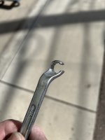
Okay, so I'd sure appreciate seeing the modified tool and where to get it to tighten and remove the nut on the HS midline bearing bolt. I could remove the VS to reduce interference but it is still a bear. A socket will slip over the nut, and from there I can probably get a small 3/8 breaker bar, but the ratchet head I have no go. On the bolt side, a crow foot fits over but not great.
I bet someone has just the thing.....????
To set the center bearing washer stack thickness to minimize binding, attach the elevators but leave out the center bolt. Then use a set of feeler gauges to find the gap thickness between the bearing and the horn (each side). Build up the washer stacks to match the feeler gauge measurements. Super glue the stacks and mark them left and right. I think I used a metal locknut rather than the bigger elastic nut so that it was easier to get a tool on it.Okey dokey, drilled the darned thing. The elevators move together no problem except that when everything is tightened up there is the slightest friction compared to without the center bolt tightened. I suspect the right washer in the right place will fix this up. But it's pretty good as is.
Okay, so I'd sure appreciate seeing the modified tool and where to get it to tighten and remove the nut on the HS midline bearing bolt. I could remove the VS to reduce interference but it is still a bear. A socket will slip over the nut, and from there I can probably get a small 3/8 breaker bar, but the ratchet head I have no go. On the bolt side, a crow foot fits over but not great.
I bet someone has just the thing.....????
Attachments
Last edited:
Learned a few things but it’s all good now after a lot of trial and error. Modified a HF offset to fit over the an4 blot head without interfering with the HS inboard tube. Used the ms21054-4 nut and a 5/16 offset worked fine at the nut with some extra washers to reduce required nut travel.
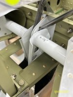
The feeler gauge was ok but when the system was loaded it wasn’t quite right. What worked best for me was adding or dropping a half washer (-L) on the right until the rod ends mated up to the hinges correctly. Put in the right bolts but didn’t tighten them. Mated the left side with the correct washers to match up to the hinges left side.
Went ahead and tightened up the center bolt first. Every iteration where I tightened the elevator bolts first seemed to create some but not a lot of friction. Starting in the middle and then doing the outboard then the inboard hinges yielded a very low friction result with everything torqued.
Not sure why it mattered but I’ve had it together and apart so many times this weekend. I’m writing this here to perpetuate my lesson learned!
2.5 washers right, 3 left.
Attachments