Van's Air Force
You are using an out of date browser. It may not display this or other websites correctly.
You should upgrade or use an alternative browser.
You should upgrade or use an alternative browser.
HIC module RV12is
- Thread starter airtwo
- Start date

There is a number of different problems that can occur. Some caused by the HIC module and some caused by the start switch module.
So if one person did chime in and said, a HIC module fixed their issue, it doesn’t mean it would fix yours (and just swapping parts is a very expensive way to fix something like this).
It’s not possible to give you a well thought out answer without a bunch more information.
Has any actual troubleshooting been done or was this just a called the Lockwood stating it cranks but won’t start and they said replace the HIC module?
I recently helped a new builder that couldn’t get his start solenoid to pick up. Turned out to be the HIC connector wasn’t fully seated in the socket. But the start circuit is fed from fuse F18 in the Rotax fuse box, then goes in and out of the HIC module, then in and out the ignition module then to the start solenoid. I’d suggest checking the pins at each of these points are fully seated in their connectors and that F18 is good. The Van’s wiring diagram shows the appropriate pins.
Sam,
Tony Kirk at Van's Technical Support sent me extensive guidance for troubleshooting an intermittent start problem back in late 2022.
Bottom line up front, his detailed trouble shooting procedure allowed me to isolate it to a bad connection (loose push on blade connector) on the bottom of the firewall mounted starter solenoid coming from the engine. It easily wiggled loose when I checked its condition so I slightly bent the female terminal sides to increase tension, reseated it and it hasn't given me trouble since.
I also dynamically balanced the prop to reduce future vibration related issues that may have caused the connection to degrade.
PM me with your e-mail and I'll forward what he sent me - or contact him at Van's Support.
Steve
2020 RV-12iS built by Lockwood
SteveSam,
Tony Kirk at Van's Technical Support sent me extensive guidance for troubleshooting an intermittent start problem back in late 2022.
Bottom line up front, his detailed trouble shooting procedure allowed me to isolate it to a bad connection (loose push on blade connector) on the bottom of the firewall mounted starter solenoid coming from the engine. It easily wiggled loose when I checked its condition so I slightly bent the female terminal sides to increase tension, reseated it and it hasn't given me trouble since.
I also dynamically balanced the prop to reduce future vibration related issues that may have caused the connection to degrade.
PM me with your e-mail and I'll forward what he sent me - or contact him at Van's Support.
Steve
2020 RV-12iS built by Lockwood
Have tried to contact Tony. He is no longer with Van's. My email is [email protected].
Thanks
Since there hasn't been any details provided beyond "no start problem", I have to make an assumption that the engine cranks but does not start.
There are two known failure modes that have previously caused some crank but no start symptoms
- a failure of the Arduino logic controller on the ign. switch module
- failed or intermittent connections on the small connector of the HIC module
Details worth knowing would be has the HIC module been upgraded previously per SB-00058?
This SB was issued to resolve the connection issues with the HIC module.
If it has, the upgraded version has a logic status LED that based on its indication, can be used to to troubleshoot potential issues with the Ign. Switch Module.
Do the fuel pumps operate normally when they are switched on before start?
The engine will not crank and the fuel pumps do not operate unless the EMS switch is on. This is a new installation and I have the new HIC. Did not know about logic status LED. Will investigate. ThanksSince there hasn't been any details provided beyond "no start problem", I have to make an assumption that the engine cranks but does not start.
There are two known failure modes that have previously caused some crank but no start symptoms
- a failure of the Arduino logic controller on the ign. switch module
- failed or intermittent connections on the small connector of the HIC module
Details worth knowing would be has the HIC module been upgraded previously per SB-00058?
This SB was issued to resolve the connection issues with the HIC module.
If it has, the upgraded version has a logic status LED that based on its indication, can be used to to troubleshoot potential issues with the Ign. Switch Module.
Do the fuel pumps operate normally when they are switched on before start?
Sounds like you need to complete SL 00072. We had this problem after installing the new HIC and this solved it.
 www.vansaircraft.com
SL-00072 - Van's Aircraft Total Performance RV Kit Planes
Optional installation of microcontroller with updated firmware for RV-12iS aircraft ignition module, if the behavior described in the service letter is observed.
www.vansaircraft.com
Sorry, I don’t have access to the LED status light chart but someone in tech-support at Vans should be able to help you with that.The engine will not crank and the fuel pumps do not operate unless the EMS switch is on. This is a new installation and I have the new HIC. Did not know about logic status LED. Will investigate. Thanks
If the engine won’t even crank, I think there is a good possibility. You have a failed Arduino on the ignition switch module, but I think the LED status light indication will help confirm whether that is correct.
Thanks, JonSounds like you need to complete SL 00072. We had this problem after installing the new HIC and this solved it.
SL-00072 - Van's Aircraft Total Performance RV Kit Planes
Optional installation of microcontroller with updated firmware for RV-12iS aircraft ignition module, if the behavior described in the service letter is observed.
I was just looking for that and somehow overlooked it.
Looked up SL-00072. May be the problem.Thanks, Jon
I was just looking for that and somehow overlooked it.
In looking at my ignition model with the master switch on I have a red LED light blinking on the circuit board. Is that normal? (Had not seen before I took the top panel off.)
Sam
The HIC Module LED troubleshooting color code table is on page 9 of the RV-12iS schematic, available on Van's Downloads page.
https://www.vansaircraft.com/wp-content/uploads/2022/10/WH-00134-2.pdf
https://www.vansaircraft.com/wp-content/uploads/2022/10/WH-00134-2.pdf
Attachments
I think the red LED flashing on the Arduino micro controller on the ignition module is normal.Looked up SL-00072. May be the problem.
In looking at my ignition model with the master switch on I have a red LED light blinking on the circuit board. Is that normal? (Had not seen before I took the top panel off.)
Sam
That is not the status LED that I had previously mentioned. The status LED is on the HIC module.
See Tony’s post above this one for details.
I think the red LED flashing on the Arduino micro controller on the ignition module is normal.
That is not the status LED that I had previously mentioned. The status LED is on the HIC module.
See Tony’s post above this one for details.
The HIC Module LED troubleshooting color code table is on page 9 of the RV-12iS schematic, available on Van's Downloads page.
https://www.vansaircraft.com/wp-content/uploads/2022/10/WH-00134-2.pdf
The HIC Module LED troubleshooting color code table is on page 9 of the RV-12iS schematic, available on Van's Downloads page.
https://www.vansaircraft.com/wp-content/uploads/2022/10/WH-00134-2.pdf
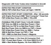
I realize that the way the chart is written it’s not all that helpful to someone not familiar with the design of the system, but what I think you need to be focused on is the expected pre-start condition.The LED on my HIC is yellow. The key on page 9 of the schematic says that pin 3 on the connector should see 5 volts. Is that the correct interpretation?
Sam
This would be with the Aircraft master switch on, but you haven’t yet turned the start key.
The status LED should be white, meaning it is in a state to allow a normal engine crank and start.
Since yours is not white, it is getting incorrect information from the Arduino on the ignition/start module (the one with the ignition key).
This indicates that there is likely an issue with the Arduino on that module, which is the subject of the mentioned service bulletin.
I think you could test this by switching on the back up battery switch that is above the ignition/start module.
If the engine cranks and starts with that switch on, then you know that everything else downstream of the ignition/start module is working properly.
At least I think that is valid info. Perhaps Tony will chime in and correct me if I’m wrong because he knows a lot more about the system than I do. (His name is on that drawing
 )
)rcarsey
Well Known Member
A couple things.. the red power LED on the arduino module (the start module) -- I believe.. should always be lit and not blink. Its showing you that it has power. If the red is blinking.. I'd be suspect.. (i cant seem to find any arduinos laying around here to test with..so im relying on Mr Google for this).
But.. if thats all OK.. then a brief explanation of the original and new (SL-000072) arduino/ignition modules is in order. On the original module, (if i remember all this right), it simply looks for bus voltage above a pre-set threshold value. If the voltage is above, then it assumes the engine/alternator is running and providing the high voltage.. and it turns off the SBB signal to the HIC module (giving you a yellow status light). Normally, that works out fine. One of the problems was that if the aircraft was on a charger for awhile, even after removing the charger, the battery might be showing abnormally high voltage still.. above the threshold.. so immediately the ignition module would think that the engine is running and kill the SBB signal.
On the new and improved SL-000072 module, the arduino takes a snapshot of the bus voltage as soon as MASTER ON.. It then looks for a rise of 0.5v increase - which happens once the alternator is running. Once running, it removed the SBB signal. The only problem this new method has, is that I think its possible that it won't detect a 0.5v increase (perhaps the battery was on a charger, and the arduino was seeing close to the same voltage as what the alternator is outputting) -- and so, the SBB signal won't ever be removed. Not a huge problem, but your fuel pumps will continue to run after engine stoppage/crash.
Lastly, if your engine has NEVER run before.. its possible that the SBB wire between the ignition module and the HIC module has been mis-pinned.. and the HIC module is never ever seeing any signal on the SBB pin. For that, you can just check continuity between the ignition module D-sub (pin #8) and HIC D-sub (pin #3) -- and sometimes the pins back out of the shell just enough not to make contact .. again, if this is a brand new installation and has never worked correctly before.
Will check. ThanksA couple things.. the red power LED on the arduino module (the start module) -- I believe.. should always be lit and not blink. Its showing you that it has power. If the red is blinking.. I'd be suspect.. (i cant seem to find any arduinos laying around here to test with..so im relying on Mr Google for this).
But.. if thats all OK.. then a brief explanation of the original and new (SL-000072) arduino/ignition modules is in order. On the original module, (if i remember all this right), it simply looks for bus voltage above a pre-set threshold value. If the voltage is above, then it assumes the engine/alternator is running and providing the high voltage.. and it turns off the SBB signal to the HIC module (giving you a yellow status light). Normally, that works out fine. One of the problems was that if the aircraft was on a charger for awhile, even after removing the charger, the battery might be showing abnormally high voltage still.. above the threshold.. so immediately the ignition module would think that the engine is running and kill the SBB signal.
On the new and improved SL-000072 module, the arduino takes a snapshot of the bus voltage as soon as MASTER ON.. It then looks for a rise of 0.5v increase - which happens once the alternator is running. Once running, it removed the SBB signal. The only problem this new method has, is that I think its possible that it won't detect a 0.5v increase (perhaps the battery was on a charger, and the arduino was seeing close to the same voltage as what the alternator is outputting) -- and so, the SBB signal won't ever be removed. Not a huge problem, but your fuel pumps will continue to run after engine stoppage/crash.
Lastly, if your engine has NEVER run before.. its possible that the SBB wire between the ignition module and the HIC module has been mis-pinned.. and the HIC module is never ever seeing any signal on the SBB pin. For that, you can just check continuity between the ignition module D-sub (pin #8) and HIC D-sub (pin #3) -- and sometimes the pins back out of the shell just enough not to make contact .. again, if this is a brand new installation and has never worked correctly before.
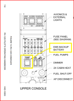
Rob is correct. Scott is partially correct, the correct switch you need to turn on to bypass the HIC Module is the "EMS BACKUP BATTERY" switch which is to the left of the Fuel Pump switches.A couple things.. the red power LED on the arduino module (the start module) -- I believe.. should always be lit and not blink. Its showing you that it has power. If the red is blinking.. I'd be suspect.. (i cant seem to find any arduinos laying around here to test with..so im relying on Mr Google for this).
But.. if thats all OK.. then a brief explanation of the original and new (SL-000072) arduino/ignition modules is in order. On the original module, (if i remember all this right), it simply looks for bus voltage above a pre-set threshold value. If the voltage is above, then it assumes the engine/alternator is running and providing the high voltage.. and it turns off the SBB signal to the HIC module (giving you a yellow status light). Normally, that works out fine. One of the problems was that if the aircraft was on a charger for awhile, even after removing the charger, the battery might be showing abnormally high voltage still.. above the threshold.. so immediately the ignition module would think that the engine is running and kill the SBB signal.
On the new and improved SL-000072 module, the arduino takes a snapshot of the bus voltage as soon as MASTER ON.. It then looks for a rise of 0.5v increase - which happens once the alternator is running. Once running, it removed the SBB signal. The only problem this new method has, is that I think its possible that it won't detect a 0.5v increase (perhaps the battery was on a charger, and the arduino was seeing close to the same voltage as what the alternator is outputting) -- and so, the SBB signal won't ever be removed. Not a huge problem, but your fuel pumps will continue to run after engine stoppage/crash.
Lastly, if your engine has NEVER run before.. its possible that the SBB wire between the ignition module and the HIC module has been mis-pinned.. and the HIC module is never ever seeing any signal on the SBB pin. For that, you can just check continuity between the ignition module D-sub (pin #8) and HIC D-sub (pin #3) -- and sometimes the pins back out of the shell just enough not to make contact .. again, if this is a brand new installation and has never worked correctly before.
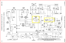
The EMS (Engine Management System) Backup Battery Switch (BBS) performs the same function as the HIC (Harness Interface Connector) Module, in that they both connect the Rotax A-Generator Bus and the B-Generator Busses together for starting (see highlights on the schematic). After engine start Rotax specifies that the busses are not connected together during normal operation. Note: There is no "backup battery", the EMS BBS (and HIC) simply tie the A & B generator busses together, the aircraft Earth-X battery lives on the B-Generator Bus, and after engine start the engine, ECU, and fuel pumps live on the A-Generator bus.
Also note: these Rotax A & B generator busses are not the same as the Rotax ECU Lane-A and Lane-B switches or circuits, which are redundant computers in the Rotax ECU (Engine Control Unit), the big black box on the right side of the F-01202B-1 tray.
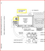
The "EFIS BACKUP BATTERY" switch located above the Ignition Switch Module is used to activate the EFIS IBBS Backup Battery, and has no connection to the HIC Module. Also note, the EFIS BACKUP BATTERY switch is only installed on the Garmin instrument panels. These circuits are also shown on the attached schematic.
See the images below for switch identification and the Electrical System Schematic, all of these are from the POH. https://www.vansaircraft.com/wp-content/uploads/2022/10/VAD-10003-RV-12iS-POH-Rotax-912iS-R11.pdf
The HIC Diagnostic LED is only on the latest AV-60009-2 HIC Module. If the HIC LED isn't white before you start the engine, you either have a mis-pinned SBB (Start Button Bypass) wire or you need to replace the AV-60007 Ignition Module Arduino as per SL-00072. See these links https://www.vansaircraft.com/service-information-and-revisions/sl-00072/ and https://store.vansaircraft.com/es-60016-7-3.html
FYI, I retired from Van's July 31st.
Good luck!
P.S., Sorry for all the TLA's (Three Letter Acronyms), it get easier to understand once you know what they all mean.
Attachments
Last edited:
Thanks, TonyRob is correct. Scott is partially correct, the correct switch you need to turn on to bypass the HIC Module is the "EMS BACKUP BATTERY" switch which is to the left of the Fuel Pump switches.
The EMS (Engine Management System) Backup Battery Switch (BBS) performs the same function as the HIC (Harness Interface Connector) Module, in that they both connect the Rotax A-Generator Bus and the B-Generator Busses together for starting (see highlights on the schematic). After engine start Rotax specifies that the busses are not connected together during normal operation. Note: There is no "backup battery", the EMS BBS (and HIC) simply tie the A & B generator busses together, the aircraft Earth-X battery lives on the B-Generator Buss, and after engine start the engine, ECU, and fuel pumps live on the A-Generator bus.
Also note: these Rotax A & B generator busses are not the same as the Rotax ECU Lane-A and Lane-B switches or circuits, which are redundant computers in the Rotax ECU (Engine Control Unit), the big black box on the right side of the F-01202B-1 tray.
The "EFIS BACKUP BATTERY" switch located above the Ignition Switch Module is used to activate the EFIS IBBS Backup Battery, and has no connection to the HIC Module. Also note, the EFIS BACKUP BATTERY switch is only installed on the instrument Garmin panels. These circuits are also shown on the attached schematic.
See the images below for switch identification and the Electrical System Schematic, all of these are from the POH. https://www.vansaircraft.com/wp-content/uploads/2022/10/VAD-10003-RV-12iS-POH-Rotax-912iS-R11.pdf
The HIC Diagnostic LED is only on the latest AV-60009-2 HIC Module. If the HIC LED isn't white before you start the engine, you either have a mis-pinned SBB (Start Button Bypass) wire or you need to replace the AV-60007 Ignition Module Arduino as per SL-00072. See these links https://www.vansaircraft.com/service-information-and-revisions/sl-00072/ and https://store.vansaircraft.com/es-60016-7-3.html
FYI, I retired from Van's July 31st.
Good luck!
P.S., Sorry for all the TLA's (Three Letter Acronyms), it get easier to understand once you know what they all mean.
It has been a while, so I should’ve looked at a panel diagram…. In my mind, I reversed the functionality of the two switches.
That's a lot to digest but very helpful. I will first check the SBB wire.Rob is correct. Scott is partially correct, the correct switch you need to turn on to bypass the HIC Module is the "EMS BACKUP BATTERY" switch which is to the left of the Fuel Pump switches.
The EMS (Engine Management System) Backup Battery Switch (BBS) performs the same function as the HIC (Harness Interface Connector) Module, in that they both connect the Rotax A-Generator Bus and the B-Generator Busses together for starting (see highlights on the schematic). After engine start Rotax specifies that the busses are not connected together during normal operation. Note: There is no "backup battery", the EMS BBS (and HIC) simply tie the A & B generator busses together, the aircraft Earth-X battery lives on the B-Generator Buss, and after engine start the engine, ECU, and fuel pumps live on the A-Generator bus.
Also note: these Rotax A & B generator busses are not the same as the Rotax ECU Lane-A and Lane-B switches or circuits, which are redundant computers in the Rotax ECU (Engine Control Unit), the big black box on the right side of the F-01202B-1 tray.
The "EFIS BACKUP BATTERY" switch located above the Ignition Switch Module is used to activate the EFIS IBBS Backup Battery, and has no connection to the HIC Module. Also note, the EFIS BACKUP BATTERY switch is only installed on the instrument Garmin panels. These circuits are also shown on the attached schematic.
See the images below for switch identification and the Electrical System Schematic, all of these are from the POH. https://www.vansaircraft.com/wp-content/uploads/2022/10/VAD-10003-RV-12iS-POH-Rotax-912iS-R11.pdf
The HIC Diagnostic LED is only on the latest AV-60009-2 HIC Module. If the HIC LED isn't white before you start the engine, you either have a mis-pinned SBB (Start Button Bypass) wire or you need to replace the AV-60007 Ignition Module Arduino as per SL-00072. See these links https://www.vansaircraft.com/service-information-and-revisions/sl-00072/ and https://store.vansaircraft.com/es-60016-7-3.html
FYI, I retired from Van's July 31st.
Good luck!
P.S., Sorry for all the TLA's (Three Letter Acronyms), it get easier to understand once you know what they all mean.
Thanks very much.
Installed new ignition module. Now have green light on module circuit board instead of red blinking light. Also the yellow light on the HIC is now white instead of yellow. Checked the eight wires on the green connector on the HIC. All appear to be in the right place and go to the right place. Checked the SBB wire for continuity and checked that it goes from pin 3 on the HIC molex connector to pin 8 on the ignition module. Next steps?
Sam
Sam
rcarsey
Well Known Member
Installed new ignition module. Now have green light on module circuit board instead of red blinking light. Also the yellow light on the HIC is now white instead of yellow. Checked the eight wires on the green connector on the HIC. All appear to be in the right place and go to the right place. Checked the SBB wire for continuity and checked that it goes from pin 3 on the HIC molex connector to pin 8 on the ignition module. Next steps?
Sam
Are you still having problems after installing the new igntion module ??
I'll assume the green light on the Ingition Module is normal -- better than red, right?
") The white light on the HIC is also normal too. You should be all set to have a successful start. Once started and you see a voltage rise, the HIC module will turn yellow -- indicating that that ignition module thinks the engine is running. The engine should start OK (Master ON, Ignition A&B ON, Fuel Pump 1 ON, EMS Battery Backup OFF, throttle set for approx 30-35%. Turn and hold ignition key until RPMs shows 1500 rpm).
The white light on the HIC is also normal too. You should be all set to have a successful start. Once started and you see a voltage rise, the HIC module will turn yellow -- indicating that that ignition module thinks the engine is running. The engine should start OK (Master ON, Ignition A&B ON, Fuel Pump 1 ON, EMS Battery Backup OFF, throttle set for approx 30-35%. Turn and hold ignition key until RPMs shows 1500 rpm).Tony, what are we going to do without you?Rob is correct. Scott is partially correct, the correct switch you need to turn on to bypass the HIC Module is the "EMS BACKUP BATTERY" switch which is to the left of the Fuel Pump switches.
................
 Congratulations on retirement!
Still having no start problem. Fuel pumps will only energize when EMS switch is on. As I understand it, the EMS bypasses the HIC module. Is that correct?Are you still having problems after installing the new igntion module ??
I'll assume the green light on the Ingition Module is normal -- better than red, right?
Thanks for your input.
Yes, the EMS bypasses the HIC Module. You can start and run your engine using the EMS switch as long as you turn the EMS switch OFF after engine start.
The LED color on the IGNITION Module Arduino is irrelevant. It can be red or green based on the Arduino manufacturer. These LEDs are Not used for diagnostics.
If the Diagnostic LED on the HIC module is White then the HIC is getting the 5 volt start signal (SBB) from the IGNITION Module, proving the SBB wire is pinned properly and the IGNITION Module Arduino is commanding the HIC MOSFETS to connect both battery busses together. It sound like both of these modules are working as they should.
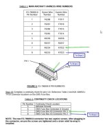
The next thing to check would be the X3 connector at the Rotax fusebox, to be sure the wires were inserted in the proper position. This is a builder-populated connector, and it wouldn't be the first time it was assembled wrong.
The schematic has all the circuit numbers. Also check that the circled solder-sleeve appears to be properly melted.

Let us know what you find.
The LED color on the IGNITION Module Arduino is irrelevant. It can be red or green based on the Arduino manufacturer. These LEDs are Not used for diagnostics.
If the Diagnostic LED on the HIC module is White then the HIC is getting the 5 volt start signal (SBB) from the IGNITION Module, proving the SBB wire is pinned properly and the IGNITION Module Arduino is commanding the HIC MOSFETS to connect both battery busses together. It sound like both of these modules are working as they should.
The next thing to check would be the X3 connector at the Rotax fusebox, to be sure the wires were inserted in the proper position. This is a builder-populated connector, and it wouldn't be the first time it was assembled wrong.
The schematic has all the circuit numbers. Also check that the circled solder-sleeve appears to be properly melted.
Let us know what you find.
rcarsey
Well Known Member
What Tony said above. Heres a more extensive list of things to check after you check your X3 connector :
!!! Ensure the 30A green generator fuse is not blown !!! (you'll have your exact symptoms, plus some other symptoms like seeing Lane A/B & Pump 1&2 green LEDs dimly lit even when switched off).
Ensure K6257 and K6282 are both connected to Generator A grounding block (the lower grounding block of the Rotax fusebox).
Ensure K6284, K6283 and K6256 are both connneted to Generator B grounding block (the upper grounding block of the Rotax fusebox).
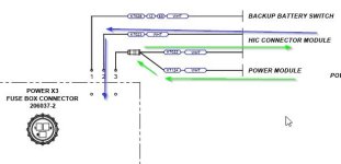
In the Rotax X3 connector that you "built", ensure K7028 is pin 1, K7023 is pin 2, and K7124/K7022 is pin 3. Ensure the solder sleeve that joins K7124/K7022 (pin3) is solid and wiggling it around does nothing (or ideally, test that pin 3 has continuity to K7022 at the hic module, and to the BLUE terminal on the Power Module).
Ensure the wires to the new-style HIC module (with the LED light) is correct.
When the HIC module is in "start mode", which it seems to be, since you're seeing the white LED light on it, effectively the HIC module is tying together two of the thick wires going to the HIC (+12v) and two of the other thick wires to the HIC module (tying aircraft ground (ground B) with the EMS ground (ground A).
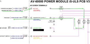
If all else fails, follow the power (see attachments). And follow the grounds (see if battery - has continuity with Ground block A during 'start mode').
!!! Ensure the 30A green generator fuse is not blown !!! (you'll have your exact symptoms, plus some other symptoms like seeing Lane A/B & Pump 1&2 green LEDs dimly lit even when switched off).
Ensure K6257 and K6282 are both connected to Generator A grounding block (the lower grounding block of the Rotax fusebox).
Ensure K6284, K6283 and K6256 are both connneted to Generator B grounding block (the upper grounding block of the Rotax fusebox).
In the Rotax X3 connector that you "built", ensure K7028 is pin 1, K7023 is pin 2, and K7124/K7022 is pin 3. Ensure the solder sleeve that joins K7124/K7022 (pin3) is solid and wiggling it around does nothing (or ideally, test that pin 3 has continuity to K7022 at the hic module, and to the BLUE terminal on the Power Module).
Ensure the wires to the new-style HIC module (with the LED light) is correct.
When the HIC module is in "start mode", which it seems to be, since you're seeing the white LED light on it, effectively the HIC module is tying together two of the thick wires going to the HIC (+12v) and two of the other thick wires to the HIC module (tying aircraft ground (ground B) with the EMS ground (ground A).
If all else fails, follow the power (see attachments). And follow the grounds (see if battery - has continuity with Ground block A during 'start mode').
Attachments
Have checked the X3 but will check again. Will let you know.Yes, the EMS bypasses the HIC Module. You can start and run your engine using the EMS switch as long as you turn the EMS switch OFF after engine start.
The LED color on the IGNITION Module Arduino is irrelevant. It can be red or green based on the Arduino manufacturer. These LEDs are Not used for diagnostics.
If the Diagnostic LED on the HIC module is White then the HIC is getting the 5 volt start signal (SBB) from the IGNITION Module, proving the SBB wire is pinned properly and the IGNITION Module Arduino is commanding the HIC MOSFETS to connect both battery busses together. It sound like both of these modules are working as they should.
The next thing to check would be the X3 connector at the Rotax fusebox, to be sure the wires were inserted in the proper position. This is a builder-populated connector, and it wouldn't be the first time it was assembled wrong.
The schematic has all the circuit numbers. Also check that the circled solder-sleeve appears to be properly melted.
View attachment 79719
Let us know what you find.
Thanks again.
Sam
@rcarsey Great and through explanation! I tend to forget that everyone doesn't understand schematics and the RV-12iS electrical system as well as we do.What Tony said above. Heres a more extensive list of things to check after you check your X3 connector :
!!! Ensure the 30A green generator fuse is not blown !!! (you'll have your exact symptoms, plus some other symptoms like seeing Lane A/B & Pump 1&2 green LEDs dimly lit even when switched off).
Ensure K6257 and K6282 are both connected to Generator A grounding block (the lower grounding block of the Rotax fusebox).
Ensure K6284, K6283 and K6256 are both connneted to Generator B grounding block (the upper grounding block of the Rotax fusebox).
In the Rotax X3 connector that you "built", ensure K7028 is pin 1, K7023 is pin 2, and K7124/K7022 is pin 3. Ensure the solder sleeve that joins K7124/K7022 (pin3) is solid and wiggling it around does nothing (or ideally, test that pin 3 has continuity to K7022 at the hic module, and to the BLUE terminal on the Power Module).
Ensure the wires to the new-style HIC module (with the LED light) is correct.
When the HIC module is in "start mode", which it seems to be, since you're seeing the white LED light on it, effectively the HIC module is tying together two of the thick wires going to the HIC (+12v) and two of the other thick wires to the HIC module (tying aircraft ground (ground B) with the EMS ground (ground A).
If all else fails, follow the power (see attachments). And follow the grounds (see if battery - has continuity with Ground block A during 'start mode').
Be careful - Van's may relocate you to Aurora to work tech support!
Through a mutual friend, Sam reached out to me for help on his issues. Having built my 12iS and being only about an hour’s flight from him, another friend, who also built his 12iS, and I visited Same to help troubleshoot his issues.
As Sam stated, he had two problems - the starter solenoid wouldn’t energize and the fuel pumps wouldn’t run. The diagnostic LED on the HIC module was also yellow. Installing my ignition module in his aircraft allowed the solenoid to energize and turn the HIC LED white. This proved his ignition module was defective; however, the fuel pumps still wouldn’t run with my ignition module.
Turning on the EMS Backup Battery (EBB) switch would energize the pumps. The EBB switch jumpers battery voltage to the A-regulator bus and ties the airframe and A-regulator grounds together. We isolated the issue to the ground circuit by turning off the EBB and manually jumping the regulator A & B grounds together - the pumps immediately ran. Jumpering the grounds at pins 5 & 6 of the HIC module also energized the pumps. This pointed the issue to the start-computer circuit, which automatically performs the function of the EBB switch.
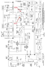
The start computer energizes FET IC01 on the HIC module to tie battery voltage to A-regulator’s bus (where the pumps are connected) and IC02, which ties the airframe and A-regulator grounds together, allowing battery current to flow through the pumps and back to the battery on startup. The white HIC diagnostic LED confirmed start power was being applied to the gates on IC01 & 02. So, it would appear IC02 is defective, has a bad solder joint, or there’s a broken pc-board trace.
The odds of two bad components (ignition and HIC modules) on the same aircraft have to be pretty high. A new HIC module will confirm this finding, but we’re pretty confident we’ve now successfully diagnosed the problem.
Sam will report back when the new HIC is installed.
As Sam stated, he had two problems - the starter solenoid wouldn’t energize and the fuel pumps wouldn’t run. The diagnostic LED on the HIC module was also yellow. Installing my ignition module in his aircraft allowed the solenoid to energize and turn the HIC LED white. This proved his ignition module was defective; however, the fuel pumps still wouldn’t run with my ignition module.
Turning on the EMS Backup Battery (EBB) switch would energize the pumps. The EBB switch jumpers battery voltage to the A-regulator bus and ties the airframe and A-regulator grounds together. We isolated the issue to the ground circuit by turning off the EBB and manually jumping the regulator A & B grounds together - the pumps immediately ran. Jumpering the grounds at pins 5 & 6 of the HIC module also energized the pumps. This pointed the issue to the start-computer circuit, which automatically performs the function of the EBB switch.
The start computer energizes FET IC01 on the HIC module to tie battery voltage to A-regulator’s bus (where the pumps are connected) and IC02, which ties the airframe and A-regulator grounds together, allowing battery current to flow through the pumps and back to the battery on startup. The white HIC diagnostic LED confirmed start power was being applied to the gates on IC01 & 02. So, it would appear IC02 is defective, has a bad solder joint, or there’s a broken pc-board trace.
The odds of two bad components (ignition and HIC modules) on the same aircraft have to be pretty high. A new HIC module will confirm this finding, but we’re pretty confident we’ve now successfully diagnosed the problem.
Sam will report back when the new HIC is installed.
Attachments