Fellow RV-4 drivers, has anyone found a convenient location to mount the red cube.
Pictures would be much appreciated.
Thanks !
Pictures would be much appreciated.
Thanks !


Send me your text or email address.Fellow RV-4 drivers, has anyone found a convenient location to mount the red cube.
Pictures would be much appreciated.
Thanks !
Mine is carb’ed. As you probably know, not much space on the RV-4 to hang anything. This is why I was looking for pics of an RV-4 install.AS Flightlines can set you up if injected with it attached directly to the spider with bracket, fittings, and hose. If carb, you be waiting till someone else responds. You might still want to call Tom at ASF even if carbed and talk to him. He has a plethora of knowledge on these things.
There is also a thread on where to put a red cube. Just not on a RV-4 specifically.
I went through the same thing with my 4.Mine is carb’ed. As you probably know, not much space on the RV-4 to hang anything. This is why I was looking for pics of an RV-4 install.


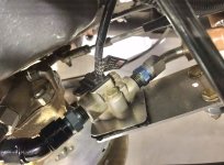
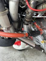
") ). It does "hang in space" but the steel fittings and short forward line support everything well. Just one way to skin the cat; and I'm sure you'll get more suggestions.
). It does "hang in space" but the steel fittings and short forward line support everything well. Just one way to skin the cat; and I'm sure you'll get more suggestions.See abovei made a .090 plate to mount it to and mounted that with adel clamps to the lower cross tubes on the engine mount. next time I have the cowl off i will send you a couple of pics.
bob buns
RV-4 N82RB
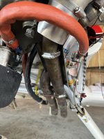
We've done them a couple of different ways on carb installs. Normally the transducer is adel clamped to one of th eengine mount tubes near the left lower dynafocal mount. Keep in mind that the cube with 2 straight nipples is 4 inches flare to flare. So that means the discharge side to the carb is pretty short---like 3.75-4 inches. Take the pump to inlet hose and turn it aft towards the firewall, then curve it 180* back to the cube. Similar to our RV10/IO540 install, but obviously shorter discharge hose.See above
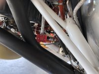
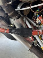
I think it’s a really bad idea to use rigid tubing (regardless of the type of material used) to support the weight of the transducer and the hose, especially at that location. There is an awful lot of movement and vibration in that area due to the distance from the crankshaft. A rigid line should never be completely unsupported along its length and needs secure attachment points at each end.View attachment 80641
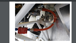
Looks scary close to the exhaust pipes, but there is actually plenty of room (after a few iterations with a patient line fabricator, thanks Tom!
Hi Bill,Vac, what's the shielding material you are using to protect the cable from the red Cube? Looks like something I would want to incorporate next time the cowl is off.
And please note my post this morning in the safety forum.