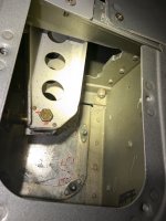
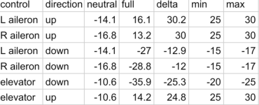
I bought an 8A that I didn't build and it's been a joy to fly. In the course of getting to know the plane better, I've looked at the range of travel of the various control surfaces, which is generally within spec. In doing so, I noticed the up elevator is at the minimum limit and the down elevator is at the maximum limit. Presumably this is due to a tolerance in the relationship of the horns to the elevator ribs, but it seems possible to adjust at the stop.
The builder clearly adjusted it already, but I'd like to know how much filing or grinding away of the stop is acceptable if I wanted to increase the travel. I feel this might help me unload the nosewheel a little more in the rollout when loaded near the forward C of G limit (common). I can't find any detailed discussion of a limit in the plans and don't want to remove any metal without being certain.
The builder clearly adjusted it already, but I'd like to know how much filing or grinding away of the stop is acceptable if I wanted to increase the travel. I feel this might help me unload the nosewheel a little more in the rollout when loaded near the forward C of G limit (common). I can't find any detailed discussion of a limit in the plans and don't want to remove any metal without being certain.