Van's Air Force

The definitive Van's Aircraft support community! Buying, building or flying an RV? Join our exclusive family of mentors and enthusiasts!

Trim sensor wiring to GEA24 - Help needed

Webb

Well Known Member
Sponsor
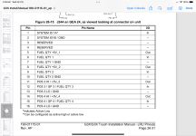
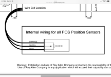
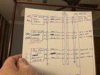
I think I have my trim servos and flap sensor pinned wrong because they don’t show on the GDU460. All sensors go thru a 9 pin CPC pigtail so pin location swap is easy and I don’t have to fool with the other wires in the J244 connector.

Roll is POS3, Flap 4, and Pitch 5, and all 3 are pinned the same.

I’m hoping this is an easy fix.

Would one of you wiring gurus please tell me how?
 

Attachments

  • IMG_1952.png
    IMG_1952.png
    467.5 KB · Views: 39
  • IMG_1955.png
    IMG_1955.png
    308.1 KB · Views: 39
  • IMG_1953.jpeg
    IMG_1953.jpeg
    2.7 MB · Views: 42
Last edited:
By "not showing" do you mean you don't see any trim or flap position indication at all? If so, that sounds like you either haven't configured the GEA 24 inputs yet, or else you have turned off the display of trim/flap position on the PFD Setup page (in which case you will still be able to see the gauges on the Engine page).
 
The boxes for the roll and trim are on screen but have the red calibration flags. Flaps box not there but I know I haven’t entered yet.

The goal was to confirm the pinning was correct so I can focus on getting the configuration done.

Is the pinning correct?

Thanks Matt
 
The boxes for the roll and trim are on screen but have the red calibration flags. Flaps box not there but I know I haven’t entered yet.

The goal was to confirm the pinning was correct so I can focus on getting the configuration done.
You have to calibrate the position inputs before the position indications will appear. If you have a wiring problem, you'll know it as soon as you start using the calibration interface.
 
The boxes for the roll and trim are on screen but have the red calibration flags. Flaps box not there but I know I haven’t entered yet.

The goal was to confirm the pinning was correct so I can focus on getting the configuration done.

Is the pinning correct?

Thanks Matt
The pinning is available in the Installation Manual rev: AW page 26-7 (pdf page 470).

Good luck
 
Hi everyone,

I have a full G3X system with a GEA 24. Initially, the trim position indicators were working perfectly—I was even able to calibrate them without any issues. However, I started noticing that intermittently, the position of both trims would suddenly go all the way to one side. When I checked the configuration page, the calibration voltage for the trim position sensors would drop to zero.

At this point, both trim positions are stuck at zero all the time. I tried measuring the voltage on pin 18 “GP1 HI / +5V” on the J244 connector of the GEA 24, but I’m getting no voltage—it reads 0V.

Any ideas what could be happening here? Is it possible that the +5V output from that pin has been damaged somehow?

Also, what’s the best way to test a Ray Allen trim potentiometer to make sure it’s working properly?

Thanks in advance for your help!
 
Back
Top