

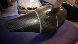
While researching how to replace my old RV-6’s 1-piece wheel pants with today’s pressure-recovery units, I came up with a good idea: by assuming the wheel axles are aligned correctly to the airplane (they are), a jig could be built to hold the brackets in rig to install them to the fairing shells. One could also make a template to roughly cut out the wheel opening using the same jig to locate the hole. And with the fairing upside down in the jig with the wheel opening on top, one could reach inside to back-drill the screw holes from the brackets to the fairing shells. None of this silly magnet and/or laser action to find the holes from the OML. And you could do all of this on a workbench instead of on your knees. And since everything is rigged to the axle, you’d be assured the fairing will fit the airplane perfectly, even though you rigged everything away from the airplane.

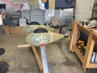
While Van’s won’t supply a STEP file of the fairings, they do have good CAD-generated drawings which I used by importing jpg’s of various views from drawing C2 into CAD and reverse-engineering, thus enabling the jig. Specifically, the Bottom View and the Side View and corresponding Section A-A of drawing C2 were used. This example is for the tapered-rod gear RV-4, 6, 7, 9 and A-models, but the same idea should work for all RV’s. Shown are the Van’s drawing views superimposed on the jig:


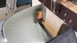
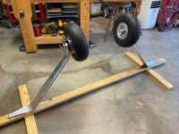
This jig uses a ‘faux’ axle to hold the inboard and outboard brackets in rig. The aft fairing shell is located by the Y- and Z-centerlines of Section A-A at the fwd/aft shell intersection plane and by the narrow trailing edge. This avoids having to eyeball the centerlines of the forward shell which is difficult due to the nose being so blunt. By using the section cut of the joint between the fwd/aft shells together with the narrow trailing edge, a more accurate centerline can be had. Even the screw hole locations are on the jig.
My faux axle was 3d printed, but you could make it from plywood too. The jig is made from Baltic birch plywood which is stable and straight. The purple removable piece which holds the axle is symmetric so that the same jig can be used for LH and RH installations. In another post, I’ll attach scaled drawings in pdf if you want to make a jig without all the engineering. Print them full-scale and use the paper patterns as templates to cut the plywood. Or you could borrow my jig, now that I’m done with it.
Note that I filled the gaps between the brackets and the inner moldline of the fairings with thickened epoxy as Mike S showed in a previous post. This gives better support for the screws as well as prevents the fairing from flexing when torquing the screws. It’s easy to do this in the jig with its great access. No need for “tweaking the brackets” as I’ve read on VAF. As you can see, the brackets fit nicely as-is.


Note the tire cutout template on top of the jig. Use a Sharpie held vertically to transfer a line onto the fairing. Doesn’t have to be perfect as you’ll fine-tune the gap later.


While Van’s won’t supply a STEP file of the fairings, they do have good CAD-generated drawings which I used by importing jpg’s of various views from drawing C2 into CAD and reverse-engineering, thus enabling the jig. Specifically, the Bottom View and the Side View and corresponding Section A-A of drawing C2 were used. This example is for the tapered-rod gear RV-4, 6, 7, 9 and A-models, but the same idea should work for all RV’s. Shown are the Van’s drawing views superimposed on the jig:
This jig uses a ‘faux’ axle to hold the inboard and outboard brackets in rig. The aft fairing shell is located by the Y- and Z-centerlines of Section A-A at the fwd/aft shell intersection plane and by the narrow trailing edge. This avoids having to eyeball the centerlines of the forward shell which is difficult due to the nose being so blunt. By using the section cut of the joint between the fwd/aft shells together with the narrow trailing edge, a more accurate centerline can be had. Even the screw hole locations are on the jig.
My faux axle was 3d printed, but you could make it from plywood too. The jig is made from Baltic birch plywood which is stable and straight. The purple removable piece which holds the axle is symmetric so that the same jig can be used for LH and RH installations. In another post, I’ll attach scaled drawings in pdf if you want to make a jig without all the engineering. Print them full-scale and use the paper patterns as templates to cut the plywood. Or you could borrow my jig, now that I’m done with it.
Note that I filled the gaps between the brackets and the inner moldline of the fairings with thickened epoxy as Mike S showed in a previous post. This gives better support for the screws as well as prevents the fairing from flexing when torquing the screws. It’s easy to do this in the jig with its great access. No need for “tweaking the brackets” as I’ve read on VAF. As you can see, the brackets fit nicely as-is.
Note the tire cutout template on top of the jig. Use a Sharpie held vertically to transfer a line onto the fairing. Doesn’t have to be perfect as you’ll fine-tune the gap later.
Last edited:


 Apparently even after 10 years the thought of dealing with this was still a bridge too far for the original builder! Anyone know of a build assist center in SoCal?!


 I like your idea, and may give it a try. Some thoughtful work you’ve done there.
 )
)

