Gavin Harrison
I'm New Here
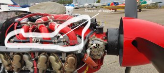
Has anybody fitted turbo charged fuel nozzle to their RV10, I0-540 X. If so what was the reason? please send pics.


"induction pressure is higher"Fuel nozzles for a turbo charged engine can be used on a normally aspirated engine if induction pressure is higher or almost the same as ambient air pressure.
This is to ensure that the air pressure around the fuel nozzle is higher than in the induction line just before the cylinder.
Fuel atomisation is dependent on a differential air pressure in the fuel nozzles.
Typically you can see this on an engine with a efficient RAM-air intake.
Good luck
I have a complete Air Flow Performance Turbo Charge system I am not using that I used only about 15 hours on the engine and willing to sell for $450 OBOHas anybody fitted turbo charged fuel nozzle to their RV10, I0-540 X. If so what was the reason? please send pics.


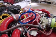
I would think if the manifold pressure is higher then upper cowl pressure, you would be blowing air and fuel out of the bleed air holes.Here is the data from my flight testing. It shows induction (manifold pressure) materially above upper cowl (plenum) pressure.
I’m not going to say my data is anywhere near laboratory quality and the MAP is measured by the Garmin and the other pressures by digital manometer.
And, obviously a little different cowl, etc than the Vans.
29-Jan 29-Jan
MSL 6500 8500
OAT (F) 60 60
RPM 2660 2400
C FLAPS closed closed
RAM AIR open open
OIL DOOR open open
TAS 258 247
IAS 229 212
GPH 24.5 18.0
MP-Ram ON 25.0 23.0
MP-Ram OFF 23.5 21.6
Ram Air Delta 1.5 1.4
Plenum pressure inHg 16.5 13.2
Lower Cowl pressure inHg 10.9 8.5
Oil Cool exit inHg-Door Open 11.7 9.1
Oil Cool exit inHg- Door Closed 11.0
Cowl Exit Temp F 154
Oil Temp F 230 223
CHT 2 F 376
CHT 4 F 340
Sound dbA 98.7
TAS Verification w 4way GPS run:
GS kts - 360hdg 284
GS kts - 90hdg 284
GS kts - 180hdg 262
GS kts - 270hdg 240
ANOTHER MEASUREMENT
H2O" pressures: cowl flaps open/closed
Plenum:11/17
Exit: 3/11
Ram: 21/25 (pitot tube mounted in center of inlet, ~2" from inlet front.
TAS 231/239 kts
#1 CHT(hottest): 316/334 F
Cowl Exit temp (cf open) 115F
OAt: 32 F
P alt:~6,000
2,500, WOT, Ram air OFF, mixture far rich
Hi Don,I have a complete Air Flow Performance Turbo Charge system I am not using that I used only about 15 hours on the engine and willing to sell for $450 OBO
You may call me at 405-612-9522
View attachment 71698
View attachment 71699
Here is the data from my flight testing.
MP-Ram ON 25.0 23.0
Plenum pressure inHg 16.5 13.2
I would think if the manifold pressure is higher then upper cowl pressure, you would be blowing air and fuel out of the bleed air holes.


Dan, thanks. It’s was super interesting collecting all the data, and all of my cooling and induction are working very well, so I’m happy.Ahhh! Thanks, missed the listing of two altitudes.
Nice work sir.
I don’t think that’s possible in my setup?I would think if the manifold pressure is higher then upper cowl pressure, you would be blowing air and fuel out of the bleed air holes.
I don’t think that’s possible in my setup?
If the reported numbers are accurate, the setup seriously needs the shrouded nozzles. Without them you would definitely be pushing fuel ), measured as deltaP (upper plenum vs freestream static), Cp would be a very low 0.46.
H2O" pressures: cowl flaps open/closed
Plenum:11/17
Exit: 3/11
TAS 231/239 kts
OAt: 32 F
P alt:~6,000

Would relatively small inlets 4.0x4.5” oval tend to a lower Cp? What is the Cp on your RV8? Hopefully these look reasonable or I’m firing the data collector.