Jeff Bost
Member
Guys,
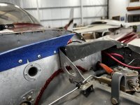
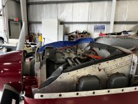
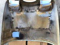
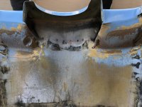
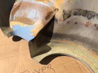
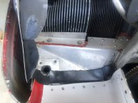
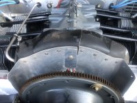
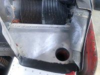
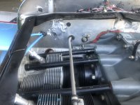
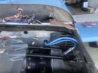
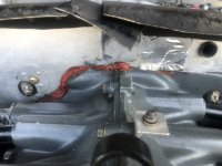
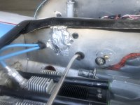
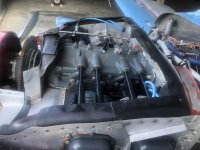
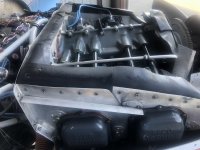
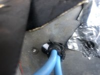
I’ve been experiencing high CHTs on 3 and 4 during cruise climb. Having to indicate 140 mph to have a chance at 400 F. I removed the top cowl this morning and snapped some pics of the baffling. Some old RTF around but I see the need for more. Big holes where the ignition harness comes through the rear. Any advice would be appreciated. I have a cockpit control for the oil cooler but it’s wired full open in the summer position. Some have suggest partially blocking the oil cooler if oil temp in acceptable. Thanks.
Jeff
Attachments
-
 IMG_4655.jpeg2.2 MB · Views: 824
 -
 IMG_4656.jpeg1.9 MB · Views: 778
 -
 IMG_4657.jpeg2 MB · Views: 753
 -
 IMG_4658.jpeg2.1 MB · Views: 714
 -
 IMG_4659.jpeg1.7 MB · Views: 692
 -
 IMG_4660.jpeg2.2 MB · Views: 660
 -
 IMG_4661.jpeg2 MB · Views: 661
 -
 IMG_4663.jpeg1.8 MB · Views: 651
 -
 IMG_4662.jpeg1.6 MB · Views: 644
 -
 IMG_4664.jpeg1.6 MB · Views: 825