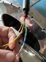
Thanks for the additional information! Those wires start at the connector in F-01406B then are routed aft with the harness to the next bulkhead F-01407 where they cross through the longerons.
View attachment 110474
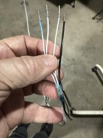
Once they have crossed to the other side they route forward and pass through bulkhead F-01406B and are pinned into the forward side of the connector that is there.
View attachment 110475
I hope this makes sense!
Ok, I'm pretty sure I get it now! But please correct me if I'm wrong.
Everything begins at plug C410P attached to the F-01406B bulkhead. It all gets tie-wrapped along the left bellcrank, then along the bottom and up the left side (right side of image) of the F-01407 bulkhead, then along the channel of the F-01486A-L stiffener all the way back to the F-01410 bulkhead.
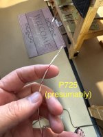
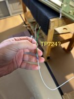
At that point, TP 725 and TP724 are picked off and everything else is run through the F-01411 bulkhead.
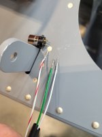
The mistake I made, which is also why I was confused, was to pull ALL the wires through to that point, including C1036 and C1037, because then I had to thread them all the way forward, back to the forward bay between F-01406B and F-01407 - right where they were to begin with. From there, C1036 and C1037 go through both bellcranks and come out the right, forward side of the F-01406B bulkhead (shown in the last inset).
If I'm on track there, I only have one more question - which is probably not your expertise if you haven't built an RV-14. If you don't know, maybe someone who has built one can answer? There are two oval-shaped holes in the F-01411 bulkhead. In the image it looks like L1082, which went through the snap bushing with the other wires, is looped back through the lightening hole, then through the small oval hole. This can't actually happen since that soldered connection won't fit through it. Maybe that's a tie-wrap depicted there?
And thank you VERY much for all your help!