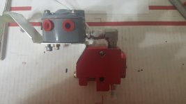
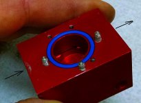
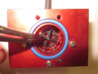
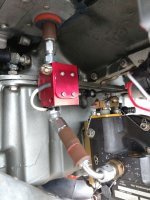
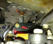
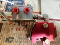
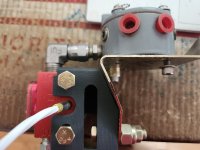
Well, well, well. FINALLY a breakthrough. After "finally" getting the needed data from Lycoming, Steve and I set out to make the necessary changes to our flow transducer bracket for the Avstar/Bendix/Precision flow dividers using the Lycoming 75009 bracket. Long story made shorter, there was an apparent change made to the bracket curve and downward angle of the steel bracket, that changed the aft side of ours. They didnt nest together properly anymore. This didnt affect its mounting to the engine, but changes our FT60 bracket. Lycoming DID change the lower hole that secures the bracket to the corresponding threaded boss on the case between the cylinders. So once we knew that it wasnt a design change, we changed our CAD drawings to accomodate that angle change. The newest 3D printed version confirms the correct modifications. So we plan to do another production run sometime after AirVenture on both the 'Avstar/Bendix" version and the AirFlow Performance version.
Sorry its taken such a long time, but it didnt make any sense to do a production run for a part that obviously wasnt going to fit. So here are the before and after pics so you can see for your self. I guess if there is a 'good' thing to come of this, it forced me to start learning CAD.
Tom