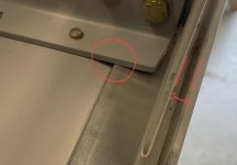
Before I remove metal and taper the edge to get the longeron to fit against the weldment, has anyone else run into this?
I can’t find anything in the instructions but it seems to be the only way to get it to fit.
The mothership was closed so I’m hoping someone has dealt with it.
I can’t find anything in the instructions but it seems to be the only way to get it to fit.
The mothership was closed so I’m hoping someone has dealt with it.