

snopercod
Well Known Member
I decided to join the 21st Century and change the altitude encoding inputs to my Garmin GTX-327 transponder from parallel to serial, driven by my Dynon D-6. Sadly, six years ago when I had the harness made up for the GTX-327, I didn't instruct the shop to add the shielded pair(?) for the RS-232 serial encoder input to Pin 19. My first plan was to extract the unused wire going to pin (socket, actually) from Pin 20, and move it over to 19. No matter how hard I tried, I was unable to get the pin extractor in the hole, so I gave up and moved on to Plan B. I begged a socket from the FBO and added a new wire.
The wiring diagrams for both the GTX-327 and Dynon D-6 were unclear, especially regarding the shield grounds. The Garmin just showed a ground symbol for the shield, but didn't specify case ground, power ground, or signal ground. I chose signal ground but, in retrospect, I don't think it made any difference. The Garmin schematic didn't show a "return" or "common" wire for the RS-232, so I guess the ground was it. I still don't know if Gamin intended a shielded pair or a single shielded wire for the RS-232 IN. The Dynon schematic didn't show shielded wire at all, but there actually was a shielded pair coming out of the harness. It contained a "return" line for the RS-232. The wire color in the manual was incorrect, but I figured out which wire was which with my Fluke.
Without going into the boring details, I connected the Encoder Out wire from the Dynon to Pin 19 of the GTX-327, and all the shields and the second RS-232 "return"? wire from the Dynon to Power Ground with ~8" #22 pigtails. I programmed the ALTENC setting on the Dynon to "Format 4" for the GTX-327, and on the transponder, set "RS-232 Input CHNL 1" to "Icarus" per the manual. I was as surprised as anybody when it actually worked. Now I guess I'll need to get another transponder check in order to remain legal.
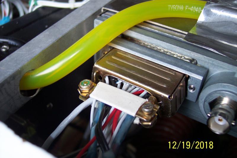
To work on the GTX-327 connector, it must be removed from the backplate with a long, skinny, screwdriver (two Phillips screws). Then the backshield clamp can be removed and the shroud retracted, exposing the back side of the DB-25 connector. Hint: The backshield clamp can NOT be reinstalled with the connector in place. Ask me how I know.
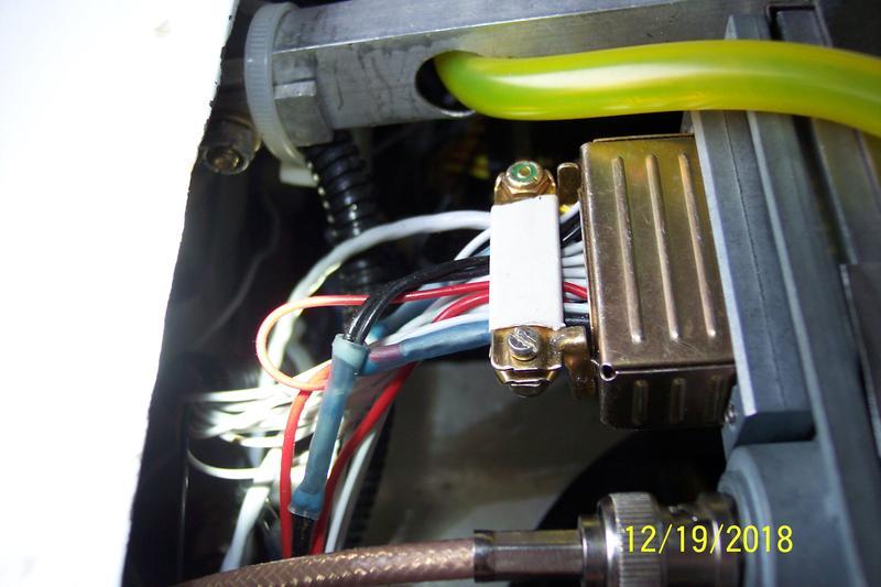
The two black wires are the "power ground" and "signal ground". You can see they are spliced together so apparently it doesn't make much difference. (Ignore the tygon fuel vent passing through the aluminum without a grommet. I'll put the grommet back tomorrow.)
The die cast "keeper" is open on the bottom, and fits over the connector and holds the connector to the back plate. It's screwed in from the inside with a long, small, screwdriver.
First, gently cut the outer jacket with an Exacto knife and pull it off, exposing the shield braid.
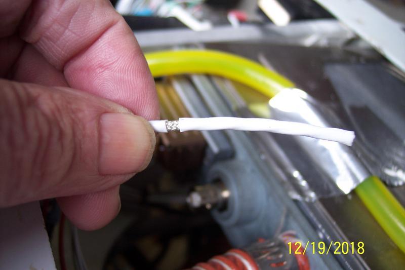
Push the braid toward the cable to make a "bird cage" at the bottom
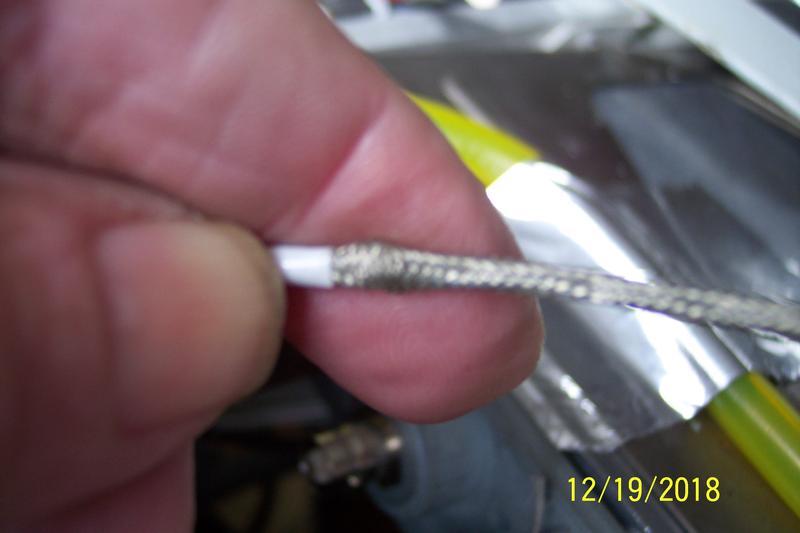
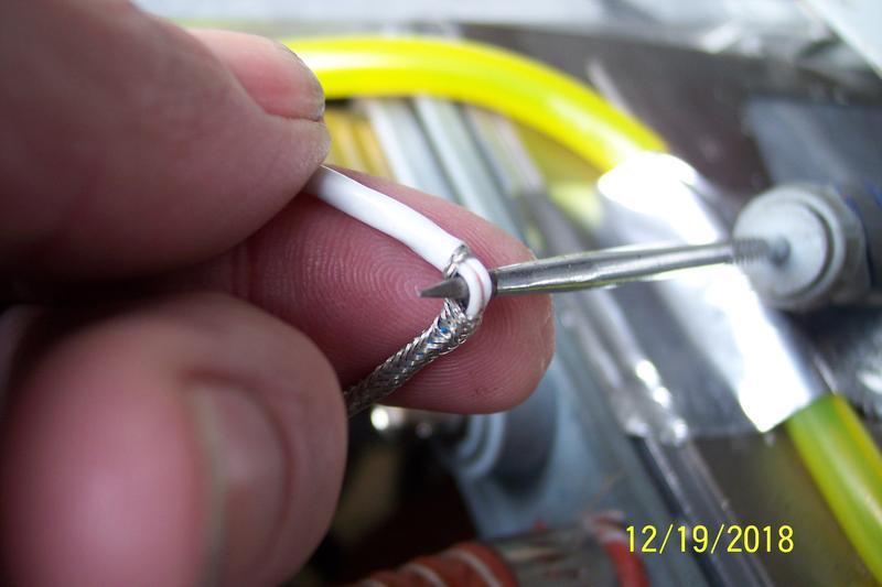
With a sharp pick, make a hole in the braid and enlarge it so you can insert the pick and pull the conductors out the hole
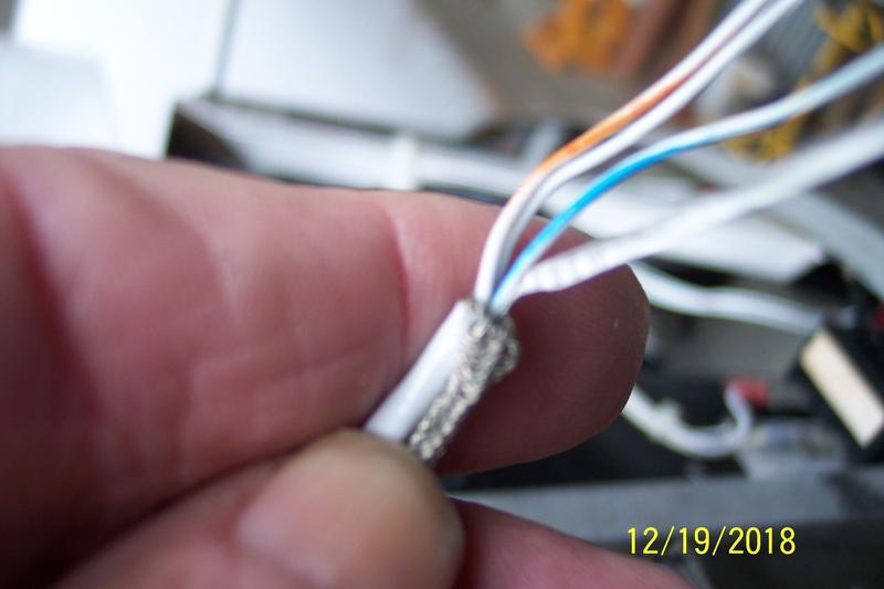
All done. Snip off the messenger strip.
Next, I soldered a #22 wire to the shield and protected the junction with heat shrink (no photo, sorry.) A solder sleeve would have been better, but I didn't have any.
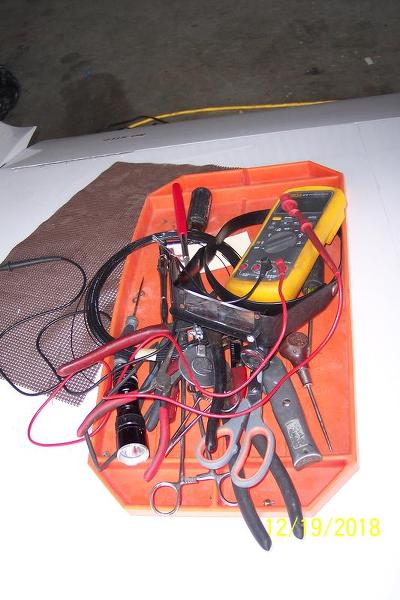
Tools
On the GTX-327, I changed RS-232 Chan 1 from OFF to (in my case) Icarus per the Garmin instruction manual
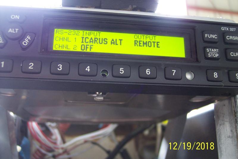
Success. The darn thing actually works in serial mode. The parallel wires are still hooked up so, in theory, I could change back by resetting CHNL 1 to "OFF"
Tomorrow I have to re-dress and Ty-Rap all the loose wires in back of the panel.
The wiring diagrams for both the GTX-327 and Dynon D-6 were unclear, especially regarding the shield grounds. The Garmin just showed a ground symbol for the shield, but didn't specify case ground, power ground, or signal ground. I chose signal ground but, in retrospect, I don't think it made any difference. The Garmin schematic didn't show a "return" or "common" wire for the RS-232, so I guess the ground was it. I still don't know if Gamin intended a shielded pair or a single shielded wire for the RS-232 IN. The Dynon schematic didn't show shielded wire at all, but there actually was a shielded pair coming out of the harness. It contained a "return" line for the RS-232. The wire color in the manual was incorrect, but I figured out which wire was which with my Fluke.
Without going into the boring details, I connected the Encoder Out wire from the Dynon to Pin 19 of the GTX-327, and all the shields and the second RS-232 "return"? wire from the Dynon to Power Ground with ~8" #22 pigtails. I programmed the ALTENC setting on the Dynon to "Format 4" for the GTX-327, and on the transponder, set "RS-232 Input CHNL 1" to "Icarus" per the manual. I was as surprised as anybody when it actually worked. Now I guess I'll need to get another transponder check in order to remain legal.
To work on the GTX-327 connector, it must be removed from the backplate with a long, skinny, screwdriver (two Phillips screws). Then the backshield clamp can be removed and the shroud retracted, exposing the back side of the DB-25 connector. Hint: The backshield clamp can NOT be reinstalled with the connector in place. Ask me how I know.
The two black wires are the "power ground" and "signal ground". You can see they are spliced together so apparently it doesn't make much difference. (Ignore the tygon fuel vent passing through the aluminum without a grommet. I'll put the grommet back tomorrow.)
The die cast "keeper" is open on the bottom, and fits over the connector and holds the connector to the back plate. It's screwed in from the inside with a long, small, screwdriver.
First, gently cut the outer jacket with an Exacto knife and pull it off, exposing the shield braid.
Push the braid toward the cable to make a "bird cage" at the bottom
With a sharp pick, make a hole in the braid and enlarge it so you can insert the pick and pull the conductors out the hole
All done. Snip off the messenger strip.
Next, I soldered a #22 wire to the shield and protected the junction with heat shrink (no photo, sorry.) A solder sleeve would have been better, but I didn't have any.
Tools
On the GTX-327, I changed RS-232 Chan 1 from OFF to (in my case) Icarus per the Garmin instruction manual
Success. The darn thing actually works in serial mode. The parallel wires are still hooked up so, in theory, I could change back by resetting CHNL 1 to "OFF"
Tomorrow I have to re-dress and Ty-Rap all the loose wires in back of the panel.

