What's new
Van's Air Force

Don't miss anything! Register now for full access to the definitive RV support community.

RV-9 with Dynon AP servo beta test

N941WR

Legacy Member
Quick note, this is a new thread split off from http://www.vansairforce.com/community/showthread.php?t=112766 due to the extreme thread drift, and yet a valuable bunch of info that deserves its own thread. MJS

Two weeks ago I installed the two new Dynon control heads, which are a great addition to the SkyView!

However, there is a potential problem with the Auto Pilot that I never experienced with all the beta testing I did on the AP.

At the top of the AP control panel is a big button labeled “AP”. After I installed the control head and powered everything up I pressed that “AP” button and the controls started banging around, especially in roll.

At the time, I didn’t think much of it. However, two days later when I was preflighting, I noticed the aileron would only travel in one direction. Meaning I could have flown right turns or straight. Obviously not a good situation.

After looking in the cockpit to make sure nothing was jamming the control stick, I removed the inspection panel in the right wing, below the roll servo.

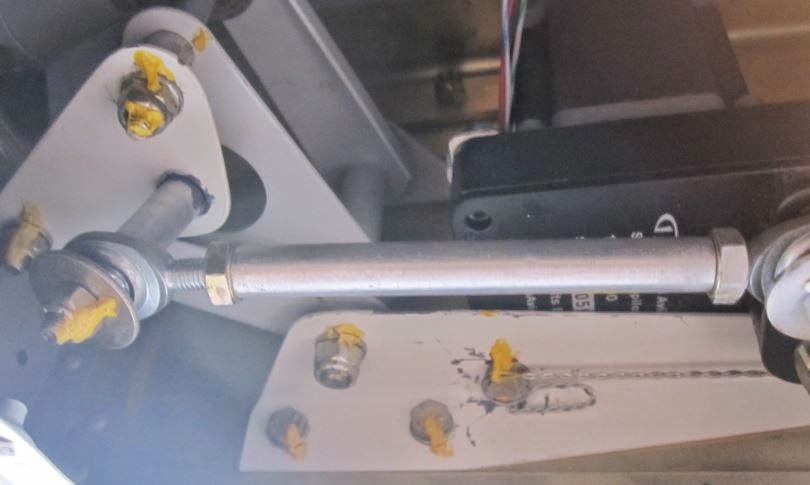
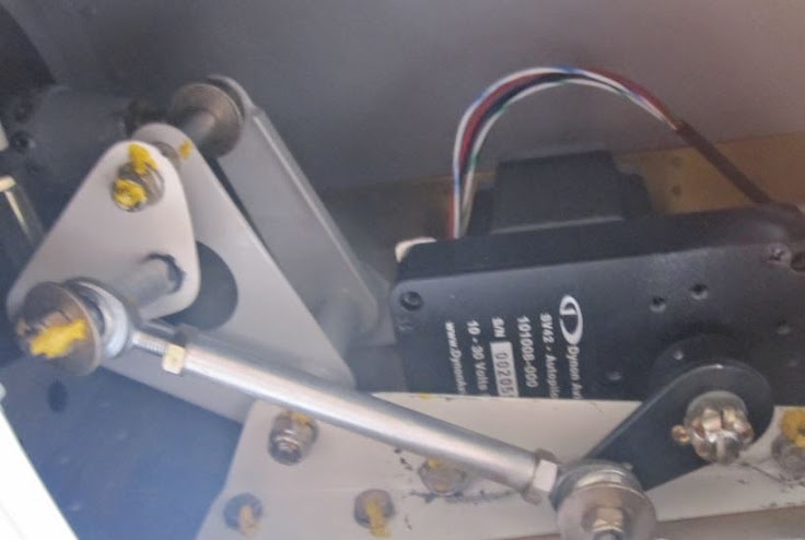
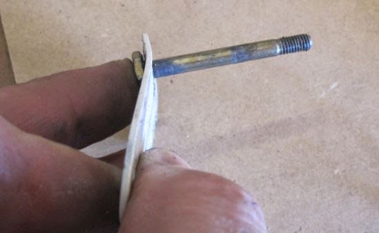
I found that the AP test function bent the attach plate and allowed the roll servo to go over center. (See pictures below.) I contacted Dynon support and was told that is why you are supposed to install the "Range of Motion Limiting Bracket". Dynon’s installation manual clearly states that they “recommend” the installation of these brackets and you can bet, as soon as I find mine, they will be installed!

My recommendations to Dynon were to fix the software so the thing won't beat the controls during the test and to redesign the attach bracket with small tabs that run along two sides to add strength and prevent the bracket from bending.

One other thing that might help is to put a large area washer between the aluminum spacer tube and the steel plate to help spread the bending load.

The roll servo arm in the "normal" position. Note the bent control attach plate.
Normal+servo.JPG


The roll servo arm in the "reversed" position, jamming the controls.
Reversed+servo.JPG


The bent control attach plate.
Bent+plate.JPG
 
Last edited by a moderator:
Normal+servo.JPG


The roll servo arm in the "reversed" position, jamming the controls.
Reversed+servo.JPG


The bent control attach plate.
Bent+plate.JPG

Bill,

Is the servo installation exactly as recommended by Dynon? That long bolt that attaches the autopilot push-pull rod to the bellcrank provides a huge amount of leverage to bend the attach bracket. I'd like to see a setup that had the push-pull rod using a very short bolt.

In any case, the structure must be strong enough to withstand full servo output, without any damage. You either need a weaker servo, or a vastly beefed up way to connect the servo to the bellcrank.

You are very lucky to have caught this now.
 
I've seen poor servo geometry lock up the controls. My Rocket did this even without the servo engaged. There are some scary installations out there and sorry Bill, but yours looks like one of them. There are some pretty extreme forces involved here due to leverage and fairly complex kinematics that many people don't understand all that well. I see several areas of Bill's that are just begging for trouble.

It's a lot more than just output torque and shear pins. Be careful with these things!
 
Last edited:
Regarding Bill's post and pictures... As someone who barely survived an A/P malfunction years ago, this gets my attention. It was a non-RV, certified A/P in a certified airplane and it still very nearly killed us.

Never - EVER - trust electronics, period. Trust electronics controlled by microprocessors even less. Program-set limits are convenient but absolutely not something you can bet your life on. You absolutely must have mechanical limits to keep hardware and firmware malfunctions from killing you. If it's physically possible for the servo arm to go over-center and jam the controls, you have to assume that it will happen at some time, and build in mechanical means to prevent it from happening. In this case you have to take into account the force a runaway servo can put on the end of that nice long AN3 bolt. It doesn't surprise me that the bolt could provide enough leverage to bend the attachment plate. You'd think the shear screw would have done its job before that happened, but obviously you can't depend on that.

I do plan to put an A/P in my plane, but will do so with the assumption that it will at some point become possessed and actively try to bring about my demise.
 
Bill,

Is the servo installation exactly as recommended by Dynon? ...

Yes, that is per Dynon's installation and matches Tru Track's installation.

One additional thing to note. The software in some installations that prevents servo activation on takeoff is dependent on GPS data. If a good lock on GPS is not present... the safety feature will not work.
....
The Dynon EFIS / Auto Pilot is driven off of air data, not GPS. It will not let you engage the AP above or below set air speeds that are set by the installer based on the designer's speed limitations.

The kicker for me was hitting the AP test button on the ground which simply "exercises" the AP as a pre-flight check.
 
Regarding Bill's post and pictures...

...You'd think the shear screw would have done its job before that happened, but obviously you can't depend on that...

One thing to keep in mind with "lever type" servos is that the output force applied to the control system can be variable. Further, when the output arm is 90 degrees to the work, the force is at it's minimum because the effective length of the arm is at it's maximum. As the arm travels through its arc, the effective length gets shorter (and leverage applied higher), ultimately resulting in a zero length arm (and ulimited leverage) at the 180 degree point (over center). So depending on where this arm is in its arc, the shear pin may be perfectly within its design load, yet the output arm is producing destructive force due to geometry/leverage.
 
Yes, that is per Dynon's installation and matches Tru Track's installation...

Bill,

While similar, the execution between your pictures and the drawing provided have some subtle, yet important differences. Without seeing the actual dimensions of the two, the spacers are much shorter and larger diameter on the Tru Trak drawing, and the rod end is on the inside of the servo arm. Both contribute heavily toward increasing stiffness of the system.
 
Yes, that is per Dynon's installation and matches Tru Track's installation.

Actually it doesn't match.
Look closely at the diagram.
The push/pull rod is supposed to attach to the servo arm on the side closest to the servo. This will allow a much shorter standoff to be used on the bellcrank.
I think a larger diam. spacer (than what is shown in your photos) is also used to help reduce the bending moment of the bolt.

On our trutrak servo installations, the spacer used at the bellcrank attach point is only about 25% as long as what you are using.

edit - looks like Michael got a post off before me...
 
It has been hinted here but I think it needs to be emphasized. It appears from the photos that this servo installation is capable of creating an over center lock condition. It appears that the length of the actuation rod is too short. The geometry of the set up must preclude over center lock. It appears this one does not

I do not think that there is an electronic mode that can lock the servo. The lock up is electro magnetic and there is nothing that can increase the strength of the magnets to the point that they can not be over ridden.
This a wrong and dangerous installation!!
 
Last edited:
Bill,

While similar, the execution between your pictures and the drawing provided have some subtle, yet important differences. Without seeing the actual dimensions of the two, the spacers are much shorter and larger diameter on the Tru Trak drawing, and the rod end is on the inside of the servo arm. Both contribute heavily toward increasing stiffness of the system.

You are correct. I will see if I can cange that tonight.

Thanks Gang!
 
Bill. The link between the servo and the control attachment must be lengthened so that the servo arm is operating between 10:00 and 2:00. It can not operate between 8:00 and 10:00 as your set up currently does.

With current set up, when the servo is at about 9:30 your controls will be locked!!!! It is only by pure luck that this has apparently only happened this one time.
 
Last edited:
Bill. The link between the servo and the control attachment must be lengthened so that the servo arm is operating between 10:00 and 2:00. It can not operate between 8:00 and 10:00 as your set up currently does.

With current set up, when the servo is at about 9:30 your controls will be locked!!!! It is only by pure luck that this has apparently only happened this one time.

Are you talking about the 2nd picture I posted? If so, you are correct, and as I stated, that is the position it was in when it jammed, after the AP bent the plate doing a self-test on the ground. Prior to the AP bending the plate, it could not go over center and I flew that way for four or five years without any issues. In fact, I had just inspected that servo two weeks prior during my condition inspection and found nothing amiss.
 
Last edited:
Bill,

While similar, the execution between your pictures and the drawing provided have some subtle, yet important differences. Without seeing the actual dimensions of the two, the spacers are much shorter and larger diameter on the Tru Trak drawing, and the rod end is on the inside of the servo arm. Both contribute heavily toward increasing stiffness of the system.

While Bill's installation does not match the TruTrak drawing linked, his setup does appear to conform to the RV9 roll servo installation drawing from Dynon which uses a 7/8" spacer.

Dynon Instructions

Apparently Dynon installation uses a longer bolt and spacer than TruTrak, and installs the rod-end bushing on the opposite side of the servo arm. I too have the Dynon installation. This is a solid argument for installing the rotation-limiter brackets. I'll be doing so ASAP.
 
Last edited:
Time to admit something?

While Bill's installation does not match the TruTrak drawing linked, his setup does appear to conform to the RV9 roll servo installation drawing from Dynon which uses a 7/8" spacer.

Dynon Instructions

Apparently Dynon installation uses a longer bolt and spacer than TruTrak, and installs the rod-end bushing on the opposite side of the servo arm. I too have the Dynon installation. This is a solid argument for installing the rotation-limiter brackets. I'll be doing so ASAP.

I was on the Dynon Beta team for their autopilot and was the person who helped them come up with the RV-9 installation. Thus, I?m not sure if their directions follow my installation, or if my installation follows their directions.

Either way, I will try installing that rod per the Tru Trak recommendation this evening and report back.

I don?t recall why I put that longer bolt in there, there very well might be an interference problem when putting the push rod on the other side of the servo arm or it could be that I simply messed up. Either way, I will report back after I get a chance to pull it apart.
 
Bill glad you read the last post before "fixing" and flying again. This is not about the length of the spacer at the attach point. Yes good practice would dictate re arranging the actuation arm to shorten that spacer.... But the most important point is to get the length of the actuation arm correct so that the geometry of the setup is correct

My reccomendation is to disassemble your current setup. Set your controls at the midpoint of travel. Then set the servo arm at 12:00 or 90 degrees to the actuation arm. Then make an actuation arm the correct length to maintain that geometry. Bolt it all together and check that the servo arm only moves throught 10:00 to 2:00 or so AND NEVER COMES CLOSE TO 9:00 while moving the controls through full range of motion
 
Last edited:
Bill. The AP servo can not bend the tab. It was the center locked geometry and you pushing the stick that supplied the force to bend that mount tab. Think of a piston at exactly T D C. You can push it down with lots of force but it will not go down until it rolls past T D C. Your servo rod was "at TDC" and there is enough friction in a powered up servo that you can not get it past TDC. Result - locked control
 
...My reccomendation is to set your controls at the midpoint of travel. Then set the servo arm at 12:00 or 90 degrees to the actuation arm. Then make an actuation arm the correct length to maintain that geometry. Bolt it all together and check that the servo arm only moves throught 10:00 to 2:00 or so AND NEVER COMES CLOSE TO 9:00.

That's exactly how it has been is set up since its installation, only I based it on the bell crank movement and not the aileron being centered, IIRC. It has been a long time since I installed that thing.
 
Bill. The AP servo can not bend the tab. It was the center locked geometry and you pushing the stick that supplied the force to bend that mount tab. Think of a piston at exactly T D C. You can push it down with lots of force but it will not go down until it rolls past T D C. Your servo rod was "at TDC" and there is enough friction in a powered up servo that you can not get it past TDC. Result - locked control

You are wrong on this point, it was the servo, in test mode, that bent the tab. Simple as that and allowed it to go over center. Once the tab was straightened, and reinstalled, it could not go over center.
 
... This is not about the length of the spacer at the attach point. Yes good practice would dictate re arranging the actuation arm to shorten that spacer.... But the most important point is to get the length of the actuation arm correct so that the geometry of the setup is correct...

Yes, the over center geometry is the most critical aspect here, but it's more than "good practice" to address the length and diameter of the spacer. All issues are conspiring to cause safety issues in this case. This installation can be improved dramatically with a little effort.
 
Bill,

While similar, the execution between your pictures and the drawing provided have some subtle, yet important differences. Without seeing the actual dimensions of the two, the spacers are much shorter and larger diameter on the Tru Trak drawing, and the rod end is on the inside of the servo arm. Both contribute heavily toward increasing stiffness of the system.

OK...

I just returned from the airport. It is as I feared, there is not enough room on the roll servo to move the bearing to the top of the arm. This leaves me with three options:

1) Make a push rod that bends up. This could allow flex in the tube.
2) Add a doubler to the existing plate. This will require longer bolts.
3) Make a new plate with tabs bent up to stiffen it. This requires me to buy some 4130 and is probably the route I will go.
 
Walt,

This is a Dyon servo, not a tru trak. There isn't enough room unless I shave the bolt head and I'm not going to do that.

I guess I could shim the servo with washers but that isn't a desirable solution.

Oops, my bad, I was thinking TT.

However looking at the servo drawings show:
TT arm height is .768
Dynon arm height .750

Thats not much difference, the TT installs on top with plenty of clearance so maybe the bearing is differnent?
 
Last edited:
It is close, very close.

Maybe a thin washer washer will do the trick. Do they make thin versions of those big washers?

Also, I like the idea of the rod dropping away, should the nut come off.
 
Yes one thin large OD washer is all you need under the head (I get them from Van's), if you're worried about a new lock nut backing off then install a castelated nut/cotter key (but not really necessary).

PS: I always use new nuts and locktite on jesus bolts :D
 
OK...

I just returned from the airport. It is as I feared, there is not enough room on the roll servo to move the bearing to the top of the arm. This leaves me with three options:

1) Make a push rod that bends up. This could allow flex in the tube.
2) Add a doubler to the existing plate. This will require longer bolts.
3) Make a new plate with tabs bent up to stiffen it. This requires me to buy some 4130 and is probably the route I will go.

Interesting that you can't move the rod end to the other side of the arm... I'm installing a Dynon servo in my Rocket right now and have room to be on that side. My geometry favors "your" side, however. Anyway, based only on your pictures and given the premise the rod end can't be moved to the other side I'd consider the following:

1. Space the servo off the mount with an aluminum sheet spacer (not washers). Move it about a tenth to .125.
2. Fabricate a new mount tab (the bent piece) out of the same material you made the spacer. Nice and thick and stiff.
3. Increase the diameter of the two spacers that hold the tab to the bellcrank as much as you can without overhanging the edge of the tab. This will give you a nice stable base.
4. Fabricate the final spacer with the same large diameter stuff you made the other two spacers from, and make it as short as possible without creating a weird angle and locking up the rod ends anywhere in the travel.
5. Install the travel limiters!

Take it with a grain of salt.
 
Last edited:
...

1. Space the servo off the mount with an aluminum sheet spacer (not washers). Move it about a tenth to .125.
...
5. Install the travel limiters!

Take it with a grain of salt.
That is good, usefull advice.

Only one problem, the idea of washers to raise the servo won't work because the critical dimension is between the top of the servo arm and the bottom of the servo body. No joy.

As for suggestion #5, as soon as I can find it, it and the one on the pitch servo will be installed!
 
This makes me wonder how many other AP servos from all the manufacturers have been installed w/o a limiter.
 
OK...

I just returned from the airport. It is as I feared, there is not enough room on the roll servo to move the bearing to the top of the arm. This leaves me with three options:

1) Make a push rod that bends up. This could allow flex in the tube.
2) Add a doubler to the existing plate. This will require longer bolts.
3) Make a new plate with tabs bent up to stiffen it. This requires me to buy some 4130 and is probably the route I will go.

Hey Bill,
Can the bolt with spacer be extended through to the second parallel plate to avoid having a bending load on a relatively thin plate? Clearly a spacer would be needed to avoid crushing.

Having said this, I admit to not having a good mental picture of the geometry and if the bolt hole projects in to material or into a lightening hole.

In my head, that would allow the bending on the bolt but a shear load between the bell crank plates to handle the force of the servo.

Just a thought.
 
Are you talking about the 2nd picture I posted? If so, you are correct, and as I stated, that is the position it was in when it jammed, after the AP bent the plate doing a self-test on the ground. Prior to the AP bending the plate, it could not go over center and I flew that way for four or five years without any issues. In fact, I had just inspected that servo two weeks prior during my condition inspection and found nothing amiss.

So I'm confused (not unusual). You say it was originally installed per the instructions, and during a ground test, it went over-center (and ended up in the position it's in in the 2nd picture)?

I can't figure out how that would happen...the only test I know of with the Dynon SV is that it sends the servos to full right/full aft (IIRC), and then to full left/full forward, asking you to confirm that's what it's doing (to avoid reversed servo action). But in the case of the ailerons, they hit the stops long before the servo arm gets anywhere *near* an over-center condition on my -7. Are you saying the servos kept running AND generated enough force to bend that part? If so...YIKES. (FWIW, I have the over-center protection thingie from Dynon installed on both my servos...still, they never get anywhere near even those limits).

I just couldn't imagine them having that much torque...enough to bend the steel bracket...before they would slip. I know I did a quick test on the ground of the pitch servo during installation, and it did, in fact, slip (with quite a loud bang resonating through the skin) when the elevator hit the stop. (Dynon concurred that's normal, btw...scared me enough to email 'em! :) ).
 
Hey Bill,
Can the bolt with spacer be extended through to the second parallel plate to avoid having a bending load on a relatively thin plate?
...

Just a thought.

Good thought but it won't work because there is a lightening hole directly above the bolt.

BTW, this looks to be unique to the -9 and maybe the -4, if the roll servo is mounted in the wing. The reason is the -9 uses RV-4 bell cranks.
 
RV-7 Flier,

You read that right. Yes, the servo generated enough torque to bend the attachment tab.

Also read my post directly above this one. The -7 and -9 have different attach points for the push rod. In addition, the -9 uses a larger roll servo (SV42) than the short wing RV's due to its longer wing. During testing I found the smaller servo didn't have enough strength to manage the roll forces in the -9.
 
So what "test" were you doing on the ground? The sort of standard "engage autopilot and verify roll commanding left and right/verify pilot can overcome servos" sort of test? And if so, you let it run all the way to the stop?

I have to admit, back when flying Pipers and Cessnas, we just did a quick check...engage it, turn the knob left/verify left yoke, turn right, overcome control forces, turn A/P off. Never let if go all the way, as far as I can remember.

And on the -7, with the Dynon SV A/P, it's inconvenient to set up and engage/test the A/P during run-up, so I don't do usually do it...hmmmm...maybe I'll start! :)

Put those servo limiters in, though...glad I did!
 
BTW, I'd submit that if the servo is not slipping when the aileron *hits the stop* (a force against the servo much higher than any it would see in flight, no?), that the slip torque value is set WAY too high.
 
BTW, I'd submit that if the servo is not slipping when the aileron *hits the stop* (a force against the servo much higher than any it would see in flight, no?), that the slip torque value is set WAY too high.

All I have to say is, you don't fly a -9 and I'm 100% certain you haven't tested the AP as extensively as I have. The settings I am using are where they need to be in flight and yes, they do slip from time to time.
 
For the rest of us...

If there are problems in the autopilot installation for a significant beta tester, what issues do the rest us need to worry about? This thread makes it seem as though it's easy to inadvertently install things in a way that's unsafe.
 
In addition, the -9 uses a larger roll servo (SV42) than the short wing RV's due to its longer wing. During testing I found the smaller servo didn't have enough strength to manage the roll forces in the -9.

This is significant, and may even be a cause of the bent steel. I have the SV32 on my 9A for both roll and pitch, and while I'm still in Phase I with not nearly as many hours as the OP, I've not had any slip problems in some very gusty conditions. In fact, Dynon recommends the SV32 for RV9 roll and pitch in its servo application guide:

http://wiki.dynonavionics.com/Servo_Application_Guide#RV-9

Could it be that the bellcrank bracket simply isn't strong enough to withstand the forces that the stronger SV42 is capable of imparting?
 
...Only one problem, the idea of washers to raise the servo won't work because the critical dimension is between the top of the servo arm and the bottom of the servo body. No joy...

I'm not quite following here Bill. Are you suggesting the airplane structure located between the servo body and the output arm is so close to the arm that the servo can't be spaced at all? I'm only suggesting a spacer here as an incremental step. Any space you gain here can be removed from that "final" spacer, which is the main goal.

As for running out of space for a bolt head if you flip the rod end- you might try using a Hi-Loc pin as a bolt. Plenty of strength with a Hi-Loc, so no worries there, but they have a very low profile head. I have a bunch of them around and use them in cases like this. If you think that may work and can't find one, provide me the set up (grip length) dimension and I'll see if I have one. If I do I'll throw a couple in the mail to you.
 
...Could it be that the bellcrank bracket simply isn't strong enough to withstand the forces that the stronger SV42 is capable of imparting...?

Maybe. This looks like a case where little details can bite you. Just eyeballing this setup, I don't like to see the total length of that attaching arm... There is a lot of force involved and an arm that long provides a bunch of leverage. That said, the main factor IMHO is the small diameter of the spacers involved, particularly that last one. Evidence supporting this conclusion is the fact that the metal bent right at the edge of the spacer. While still far from ideal, I'd suspect that simply increasing the diameter of the spacers will increase the stiffness of the system enough to prevent the servo from bending the metal.
 
Maybe. This looks like a case where little details can bite you. Just eyeballing this setup, I don't like to see the total length of that attaching arm... There is a lot of force involved and an arm that long provides a bunch of leverage. That said, the main factor IMHO is the small diameter of the spacers involved, particularly that last one. Evidence supporting this conclusion is the fact that the metal bent right at the edge of the spacer. While still far from ideal, I'd suspect that simply increasing the diameter of the spacers will increase the stiffness of the system enough to prevent the servo from bending the metal.

I agree with you. However there may be hundreds of -9's flying with this installation per the Dynon instructions. We seem to be on a path of suggesting that the manufacturer's installation instructions and parts are inadequate, which may not be the case. The OP has a non-standard installation that will produce more than a 50% increase in force over the standard installation, using the same hole in the servo arm. Given the same geometry and test routine, would the SV32 have been capable of damaging the steel brackets? Who knows. But thankfully this is the first case we've heard of.
 
I agree with you. However there may be hundreds of -9's flying with this installation per the Dynon instructions. We seem to be on a path of suggesting that the manufacturer's installation instructions and parts are inadequate, which may not be the case. The OP has a non-standard installation that will produce more than a 50% increase in force over the standard installation, using the same hole in the servo arm. Given the same geometry and test routine, would the SV32 have been capable of damaging the steel brackets? Who knows. But thankfully this is the first case we've heard of.

I think that the drawings are based upon Bill's setup...

In any case, this design ignores some fundamental mechanical design elements. Is the stiffness of the system "adequate" for an SV32? Perhaps, but it might also be right on the edge. But clearly it's not adequate for a SV42.

At any rate, there are two absolute truths in any servo installation:

1. A servo can not be allowed to bend any part of the structure or linkage through output power;
2. In the case of servo lockup and subsequent pilot override, the shear pin or other failsafe must give way before the linkage or structure.
 
Last edited:
Bending load vs shear or tension

There are some scary installations out there and sorry Bill, but yours looks like one of them.

There are so many issues with this design; it is hard to know where to begin. Primarily, always minimize bending loads, design for the loads to be passed in shear or in tension. These induced bending loads should be designed out both for the bolt and the bolt's interface. This arrangement performed exactly as would be expected, which is not the way it was intended.

I looked for a good basic reference on joint design and found this one: https://www.fastenal.com/content/feds/pdf/Article - Bolted Joint Design.pdf . It is not all you need to know, but it is a start.

From a design stand point; the structure should be able to withstand all applied loads plus margin. This would include, servo, pilot input, friction, and wind gusts for starters. To say it another way, the full force application of the servo should not be able to deform the joint or bracket and should have a safety factor or 2 for a skilled kinematic and stress analysis, or S.F of 4 for a hand analysis.

I would expect that this deformation is repeatable. Put a new bracket on, apply the load and watch it bend. I believe this is a faulty design. :eek:
 
Oops, my bad, I was thinking TT.

However looking at the servo drawings show:
TT arm height is .768
Dynon arm height .750

Thats not much difference, the TT installs on top with plenty of clearance so maybe the bearing is differnent?

The Dynon arm height is .75, the arm itself is .12 thick, so the nominal distance between the body and arm is .63.

I have a bunch of rod ends laying around and the thickest one I have measured .495. The stacked height of a Hi-Loc (used instead of an AN bolt) and an AN970L washer is a scant .070 for a total of .565. This total stack up clears the body of the servo by .065, though I'd like to see a thinner rod end used just to allow as much clearance as possible for eventual gear train wear, slop and possibility of trapping FOD.

Flipping the rod end (and significantly reducing/eliminating the spacer on the bellcrank) would definitely improve the geometry of the -9 installation, but people need to keep in mind that the rod end/bolt is running at significantly reduced clearance to the servo body and the possibility of a hard jam is increased. I think it's a good way to go, but in the interest of full disclosure it should be noted that if the bolt backs out a little or something gets stuck in there, then the shear pin won't help.
 
Last edited:
This makes me wonder how many other AP servos from all the manufacturers have been installed w/o a limiter.

Which one is the limiter, looking at the picture/drawing I can not figure out which one is the limiter of the arm.
 
Which one is the limiter, looking at the picture/drawing I can not figure out which one is the limiter of the arm.


I contacted Dynon support and was told that is why you are supposed to install the "Range of Motion Limiting Bracket". Dynon’s installation manual clearly states that they “recommend” the installation of these brackets and you can bet, as soon as I find mine, they will be installed!

Sounds like it was not installed at all, so probably not in the photo.
 
Bill,
Thanks for bringing this to our attention. Clearly we're concerned to hear about any failure like this.

As has been identified, this is why we recommend the over-center limiting bracket on every install. Even in an install that appears that it can not go over-center, the bracket is a great backup to unexpected failures. While it isn't in the drawing, it is in the text requirements for the install and included with every servo we ship.

Our mechanical team at Dynon is looking over the install and doing some of our own tests to see if we can re-create this issue using only the strength of the servo (about 4 lb/ft of torque).

A few bits of misunderstanding to clear up.

1) This was not in a test mode. You can engage the AP on the ground, by design. At zero airspeed, the AP can be engaged. This allows you to still use the AP if your pitot system fails and goes to zero. So when you engaged on the ground, you engaged it in a standard mode and it attempted to roll the plane to the heading, track, or course you had selected. The AP will disengage when the airspeed hits 20 knots, so you can't take off with it on accidentally.

There is a self-test mode which can only be accessed via menus in the system, not in any kind of normal operating mode. This does not cause the controls to travel to the limits.

2) The shear screw does not exist to limit the force of the servo. If it did, you could break the shear screw with your knee when you reached over to grab your lunch. The shear screw is stronger than the servo motor and is only there to protect from a geartrain failure. In normal operation, the servo motor itself is limited in torque, and can be overridden without breaking the shear screw. Just grab the stick and override it. So it is not unexpected that the shear screw didn't break.
 
Stand by for a fix.

I am going to work up a fix and will report back. (As well as install the limiter.)

Give me a week or two to fabricate, install, test, and document the fix.
 
Dynon,

Regarding activating the AP with zero airspeed, you also have the GPS ground speed. So, why allow the SV to activate, if both are zero?
 
...Our mechanical team at Dynon is looking over the install and doing some of our own tests to see if we can re-create this issue using only the strength of the servo (about 4 lb/ft of torque)...

Are you considering the output of the servo with the load only at 90 degrees, or through the full range of motion? It looks like with the linkage geometry of this particular installation, the force applied rapidly increases as the servo reaches the end of travel due to the effective reduction of output arm length. Depending on where the aileron linkage hits it's hard stop, the servo could be applying 10 (or more) times the force it does in level flight.
 
Back
Top