What's new
Van's Air Force

Don't miss anything! Register now for full access to the definitive RV support community.

How do I get that rod end bolt onto the prop governor actuator?

chepburn

Well Known Member
Hi all,
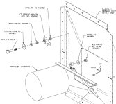
Is there a 'trick' to attaching the control rod end to the prop governor actuator arm? (Hartzell governor) I am using Van's mounting bracket and control cable....According to the plans, I am to install the bolt with the head towards the governor...the bolt is too long to get between the actuator and governor body, no matter where the actuator is positioned in it's travel...
The governor, bracket, and control cable are in place on the engine.
I didnt think it was appropriate to dissassemble the actuator arm to get the bolt into place, so I thought I would ask those know better before I do something I regret.

Chris
 
Chris, no you do not need to diassemble the actuator arm. If the arm is clocked properly for your application, and the bolt won't fit, turn it around. The adage about all bolts being heads up and forward does not work in all scenarios. Just make sure you assemble it correctly with the proper washers and self-locking nut ( a high heat one is a good idea for this application).

Vic
 
I had the same problem

and turning the bolt around was not an option because the threaded end would interfere with the screws on the governor. What I did was remove the bolt that clamps the arm to the governor axle, then slide the arm aft juuuust a little bit enough to slide the bolt in place without completely removing the arm. slide the arm back, put the bolt back and you are done. The biggest PITA was saftety wiring that arm clamping bolt again with the engine and all the accesories mounted....

Hope this helps,

Marco
 
Well, I took another try at it... and I re-read the instructions that came with the bracket (what? instructions?) Anyway, if I remove the bracket from the governor to get it out of the way, the bolt has enough clearance to be inserted into the rod end. However, it hits the boss on the governor that hold the rpm adjust.
The instructions ALSO say that I should loosen all of the mount screws on the governor front plate so that I can rotate the housing for clearance.
Fine. However, the instructions look like they are written for the MT governor, not the Hartzell, so I am not comfortable just jumping right in and rotating that housing.... isnt it aligned at a given angle? or is the housing position relative to the stops on the front plate not relevant? I will be calling Vans today to ask the same question.

So...is it OK to rotate that housing? or am I going to lose the calibration? (I know I will have to recalibrate the fine setting once the engine is running)

Thanks for any help....
 
Hartzell installation instructions

Chris,

We provided Vans installation instructions for our governor that are dependent on the aircraft model. It sounds like you are missing those instructions?

Please e-mail me directly at [email protected] so we can get you on the right path.

Les
 
What I ended up doing...

Les was kind enough to provide me with some additional instructions.
For those of you who follow, here is what I ended up doing:

Well,
I bought an S-1-10 Hartzell governor from Vans.
The instructions that came with the VA-153 Cable bracket looked like they were written for the MT governor, so I posted some questions here, and got some suggestions on how to install the bracket.
Long story short, they way my governor arrived, it was impossible to get the bearing/bolt onto the actuator arm as Vans drawings indicated.

IMG_3596.jpg


No way that bolt is going in.

Here is the orientation of the governer actuator as recieved:

g1.JPG

Notice that if the arm swings left, the bearing and bolt are going to strike that stop screw holder...

This is where the instructions come into play, they tell you to loosen the six cap screws so that you can rotate the governor head. Well, if you have never seen inside of a governor, you have to wonder...am I screwing up this thing's calibration?
The Hartzell folks (Thank you Les) were kind enough to send me some instructions on loosening these cap screws and installing the bracket.

I also called Hartzell technical support, and they were VERY helpful in talking me through this.

A couple of things to note:
The drawings will most likely NOT match the way your arm is positioned on your governor.
Rule 1:
The clock orientation of the arm can be changed. It will NOT mess up the governor's calibration.
Rule 2:
When you loosen those screws and rotate the head, you MIGHT dislodge the O-Ring on the governor head.
I did...I almost didn't notice it when I was about to tighten those screws back in. That would have been bad.
Rule 3:
The governor WILL NOT EXPLODE if you completely remove all six scews and gently remove the head to reseat and check that O-Ring.

This is what it looks like inside:

IMG_3605.jpg


OK, the important things are:
1: If your control arm travel sweeps by the bosses that mount the stop screws like in the first picture, you will need to loosen the nut holding the arm down so that you can lift it on the shaft and rotate it so that it can travel fully without the rod end bearing/bolt hitting anything. See picture below...notice the arm has been relocated by about 90 degrees compared to the first picture above. Remember to re-torque that nut properly.
2: In order to orient the bracket correctly, it must be pointing towards your control cable. In my installation, the cable is coming into the governor from the left, and below by about 45 degrees. That large governor bolt at the rear in the picture below is at about the correct orientation if the governor is on the engine. So the arm is pointing at about 12 o-clock to get full travel from the control cable.
3: You will NOT be able to get the bolt and bearing on with the bracket in place, so temporarily attach it to see how everything works

IMG_3606.jpg


If you leave the bracket off, you can get the bolt in....

IMG_3600.jpg


Here is what the bracket looks like in place and configured so that everything clears, and the arm can move full travel freely. Note the bracket is pointing away from the large bolt on the governor. Also note that the control rod will be able to move full travel freely. (This control rod is a temporary rod used for fitting, it is NOT a control cable)

IMG_3608.jpg


Here is is in place on the engine.
The rod is pointing down at about 45 degress.

IMG_3611.jpg


Here is the control cable where it will be placed.

IMG_3612.jpg


Note, I am going to have to attach the cable to the bracket, then the cable/ rod end to the governor actuator arm, THEN finally the bracket to the governor. Hartzell recommends the use of threadlocker primer, then Loctite 242 on those cap screws when they are reinserted .

Thats it. Hope this helps someone else.
 
Thank You

Thank You, Thank You, Chris Hepburn!

I am installing this Hartzell governor today and was pulling my hair out over the same situation as yours.

I followed your excellent instructions and pictures, and got it done in 10 minutes.

I will send Les an email to get the torque for the lever nut and the 6 housing screws, unless you have them?

You really saved my bacon, thanks again for taking the time to document your work in a quality manner.
 
See my reply on a related thread.

I have an MT governor and have the same issues - the bolt fouls whichever way you try.

Ended up reversing the lug that supports the cable and brought the cable on the outside - not through the bracket. Worked fine.

The old bracket was much better and this is just not up to Vans standard in any way.
 
Thanks Chris

Your pictures and explanation really helped out.
Just talked to Steve Reindel at Hartzell and he was kind enough to send the governor maintenance manual that has a parts diagram breakdown and all of the torque values.
The control shaft nut (S models only) 72-96 in lbs
The head to body cap screws 21-25 in lbs
I can forward the PDF manual to anyone who needs it. It's dated 12 January 2011. Vans "instructions" are dated 12-01.
 
MT prop Govenor

I too have a problem with the bolt being too long to attach the prop gov cable to the arm. I too have learned that you cannot mount the bolt the opposite way as it hits/interferes with the screws that mount the top ring of the gov. I am about to try the suggestion of loosing the arm attach screw and carefully lifting the arm to gain the minute distance to clear the bolt but it seems as some have gotten the bolt in without doing this and I wanted to explore any other responses before I lift the arm. I have a tendency to screw up more times than not. Any other suggestions would be greatly appreciated. [email protected].
 
I just ran into this issue with my Jihostroj (same as PCU5000X). With this governor, I found a solution not requiring disassembly:

When the arm is rotated counter-clockwise (low speed, I think), the shaft/arm lifts away from the governor, creating more clearance for the bolt. But the cable bracket still blocked the bolt. So I marked the proper clocking, loosened the 6 screws enough to twist the mechanism, rotated it enough so when the arm was moved to the low speed position, it was clear of the cable bracket, then slipped the bolt in. Rotated back to the mark and tightened the screws again. Easy!

http://www.prettybits.com/oneBigList.cfm?sectionID=53&entryID=644&projectID=1
 
The governors are not quite the same - they are similar !!!

MT fell out with Jihostroj according to them last Sun n Fun and now make their own or source it elsewhere.

http://www.propellergovernor.com/faq/

Explanation at the bottom I believe :rolleyes:

The bolt won't fit as described on the MT governor without disassembly.

If you carefully reverse the 90° bend in the cable mount and don't bring the cable through the slot, it works just fine with the bolt coming in from the outside.

Email me for a snap.
 
Last edited:
I'd be a little worried about re-bending that tab another 180 degrees after it was already bent 90 degrees. Another option would be cutting the tab off and welding another one on the aft side.
 
How do you get that AN3-11 Bolt thru the MT Govenor Arm

2 years later but I can't get that -11 bolt thru the MT Govenor arm. How did you do it? Instead of cutting the wire and loosening the arm to slide it out, how about one of these solutions. The interference of the bolt head is about 1/16".

1. Could I grind down the thread end of the bolt to make it shorter? Shoulder would still be long enough.
2. Or could I just use a -10 bolt. It will fit in. Do I need 2 washers on the inside?
3. Or what about grind down one edge of the bolt head to get it to pass by the housing. Would that weaken the bolt too much?
4. What if I filed the edge of the housing and the bolt head each a little to get the bolt to pass in?

Are removing the arm from the shaft or reversing the bracket the only solutions?
 
Chris, no you do not need to diassemble the actuator arm. If the arm is clocked properly for your application, and the bolt won't fit, turn it around. The adage about all bolts being heads up and forward does not work in all scenarios. Just make sure you assemble it correctly with the proper washers and self-locking nut ( a high heat one is a good idea for this application).

Vic
How do you get that AN3-11 Bolt thru the MT Govenor Arm

2 years later but I can't get that -11 bolt thru the MT Govenor arm. How did you do it? Instead of cutting the wire and loosening the arm to slide it out, how about one of these solutions. The interference of the bolt head is about 1/16".

1. Could I grind down the thread end of the bolt to make it shorter? Shoulder would still be long enough.
2. Or could I just use a -10 bolt. It will fit in. Do I need 2 washers on the inside?
3. Or what about grind down one edge of the bolt head to get it to pass by the housing. Would that weaken the bolt too much?
4. What if I filed the edge of the housing and the bolt head each a little to get the bolt to pass in?

Are removing the arm from the shaft or reversing the bracket the only solutions?
Hi Steve, you are absolutely correct in that these are the only options for the MT Govenor to get the -11 to be inserted. I had considered the same exact 4 points you mentioned above last night (2/5/2024) before reading your post. I also removed the course pitch screw to get a bit more clearance and still the -11 bolt cannot be inserted into the arm without considering grinding the bolt or the housing. At this point I have the -10 inserted. A portion of the threads however are in the arm even with one less of the washers. Even as specified, the -11 would still have some of the threads in the hole of the arm.
 
I've never understood why this is such big deal. Mine didn't work that way either, so I just flipped it around the other way. My governor is a Jihistroj, which I believe is basically the same thing as a MT. Maybe it doesn't work out the same way on the hartzell?

I've looked at it quite closely. If the cotter pin magically evaporates and the nut unscrews itself I think it is possible for it to get hung up on the screws on the governor housing before it fall off completely, which would limit your rpm control, but it's not exactly catastrophic.

Plus, the chances of a castle nut with a cotter pin failing are so remote as to be almost nonexistent. Heck, the axle nut for the left main is trying to unscrew itself any time the wheel is turning and you don't see left mains bouncing down the runway.

Please enlighten me if I've missed something here.
 
Are people using a castellated nut and cotter pin here? Not a bad idea and certainly nothing wrong with doing so, but my plans show a MS21042 locknut there:

1709742627743.png

Admittedly, the plans are inconsistent about the use of castellated nuts versus locknuts on rod end bearings in the FWF area... drawing OP-22 shows castellated nuts for throttle and mixture, but OP-26 shows locknuts for the same controls.
 
Are people using a castellated nut and cotter pin here? Not a bad idea and certainly nothing wrong with doing so, but my plans show a MS21042 locknut there:
I put an IO390 in my 7 so I referenced the RV14 engine installation data. Section 50-30 calls out a castle nut and cotter pin at the prop governor so thats what I went with. But then again, it also shows the bolt head inboard...
 
Plus, the chances of a castle nut with a cotter pin failing are so remote as to be almost nonexistent. Heck, the axle nut for the left main is trying to unscrew itself any time the wheel is turning and you don't see left mains bouncing down the runway.
Unless you're United :)
26e15df83eb7cb4748de674c8b9566ab
 
Back
Top