What's new
Van's Air Force

Don't miss anything! Register now for full access to the definitive RV support community.

SB 14-01-31; RV-6, 7, 8

Smooth edge dressing to keep from having stress risers probably is the key. Even samples with relief notches, (done correctly or otherwise) have cracks..

My edges are absolutely rounded and smooth, but still cracked, so I don't think that is the answer.
 
One could consider shot peening - glass beads actually. Here is a reference that documents increased fatigue life of 10x with a level of peening. More research on the exact alloy is required before proceeding. Test strips would need to be made and prestress made. Post peen would need corrosion prevention treatment.

http://www.shotpeener.com/library/pdf/1999025.pdf

Test specimens will have to be made and prestress approximated to yield improvement. Glass beads MUST BE CONTROLLED to keep them out of the structure and causing even more damage.

If this is used and successful, then the SB yearly inspection would apply, but life would be extended by 10x and the fix maybe never needed. If not, then no worse and inspect until cracked then "comply fully"

While this is a legitimate means of extending the fatigue life, this is not a recommendation, simply an intellectual alternative for some situations where the HS is hanging on the wall.
 
However I am inclined to believe that the problem is not with the relief notches per se. Logic would suggest that they should distribute stresses rather than concentrating them.

Where the resulting cross section is the same, I would agree. But many of these notches cut very deeply across the shear web... In some photos posted here, it looks like almost 1/4 inch in from the flange. That has to reduce the load carrying capability of the shear web somewhat. So yes, a well smoothed, rounded notch could better carry the load without cracking, but it will have to carry a proportionally higher load due to the narrower cross section.

Have we seen any cracks on parts without notches, but with smooth rounded corners?

Rob,

I've built a bunch of these Stabs over the years and never put in the notch because it has never been on my plans (I think). I have always treated that corner with care while building. I'm not seeing any cracks in the ones I've built that way.
 
One thing that has not been discussed in this thread is the "grain" of the sheet metal. When I started my RV4 thirty years ago a very experienced airframe mechanic informed me about the grain of aluminium. When possible it would be better to form the radius of a bend across the grain of the sheet. Although a larger radius bend negates the necessity for this consideration the grain is still something to be concerned with. You can see the grain on the sheet as the very fine almost invisible lines on the surface. These are a function of the manufacture of the sheet. Try bending a tight radius with and against the grain and you will find that it cracks much easier when the grain is "with" or parallel to the bend.
The problem with making bends like this is that it is not practical to make all the bends 90 degrees to the grain as you would rapidly run out of useable parts of the sheet metal. Now to the parts in question.
In post 191, you can seen the grain in the bottom picture, and yes the crack follows the grain. I have not examined all the pictures but as this particular part is fairly long, probably over 48", the typical sheet width, then I suspect that all these spars are bent with the grain.
I am not a professionally trained sheet metal person but after 10 airplanes I certainly have a feel for metal and I wonder if "grain" could be a factor in these spar cracks.

very good, I do remember on the fuse kit, making a part for the rear spar, that says to make it with the GRANE running a particular way.
 
Rob,

I've built a bunch of these Stabs over the years and never put in the notch because it has never been on my plans (I think). I have always treated that corner with care while building. I'm not seeing any cracks in the ones I've built that way.

The -7 HS has the slot, at least mine did, but the -8 HS does not.

You'd think a smooth slot would prevent what is happening.....it is not. (See Walt's post #203)

I wonder if the SB could have been a bit more selective in defining on which aircraft the cracks are occurring. So far there are no reports of a crack where the slot is absent, at least not that I have read.

I don't have any "slots" (early plans did not call for it) but attempted to make a nice smooth transition area here, it still cracked.

IMG_5031.JPG
 
Smooth edge dressing to keep from having stress risers probably is the key. Even samples with relief notches, (done correctly or otherwise) have cracks..

Flexing of the structure is what is going to create the cracks. The poor deburring just gives it a place to start. There is obviously some flexing happening and it is concentrated in this area. Van's fix is to beef up and strengthen the area.
 
So far there are no reports of a crack where the slot is absent, at least not that I have read.

I know of at least one that was reported - not sure if it is on this thread though.

That's the problem with a long thread like this - it's very hard to capture it all.
 
Last edited:
Notches, difference in the 7 and 8

Now that I have caught up on all the posts and info, perhaps I can offer some reasoning for the notches being or not being present between the models.

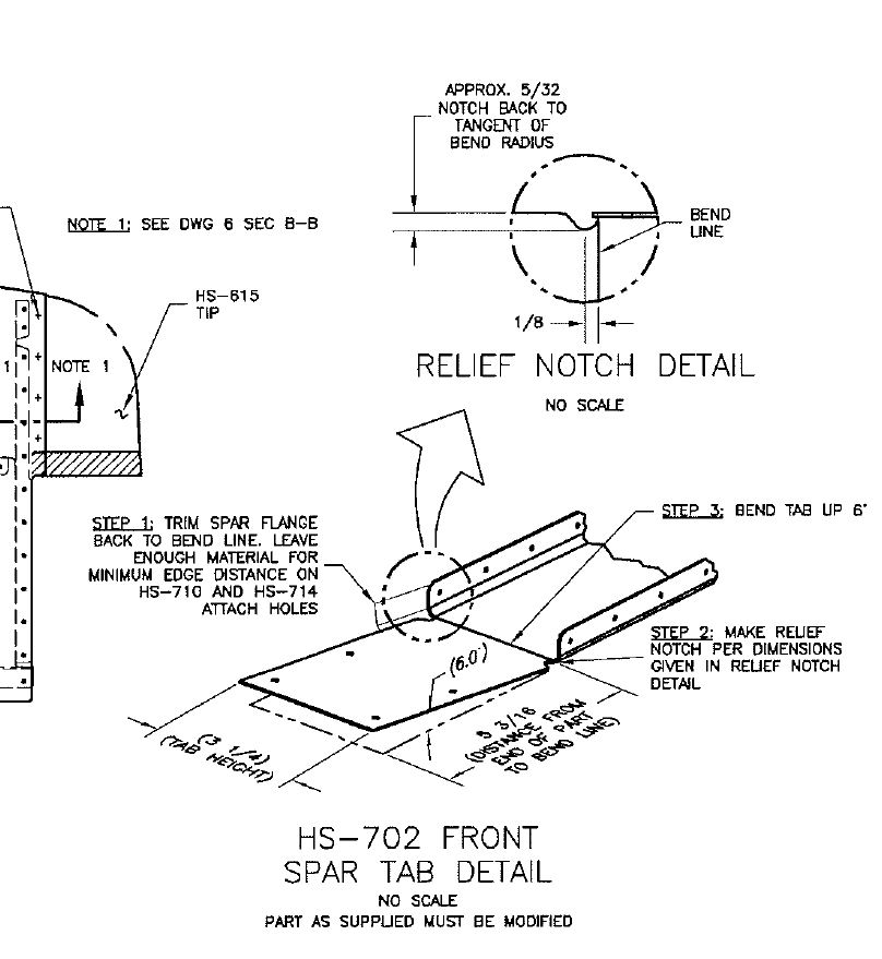
The -7 and -8 share many of the same parts but the fuselage at the HS is not the same shape. The 7 is obviously wider and the skins are of a different profile at the HS root. These differences can be accounted for in either stamping different spars or having the builder modify them to suit. Van's clearly chose the latter.

DWG-3-Snip.jpg


As you can see in the DWG 3 snippet, you must modify the part formed for the -8 to meet the needs of the -7. At the same time, the notches are called out to remove the radius portion of the spar after the flange is removed.

I looked at my HS and I did a decent job of radiusing the notches, but I will be complying with the SB as it is WAY easier to do it off the plane and be worry free. I don't like the idea of undoing work...but who does.

I presume that the -6 may not have notches because that part was made to match the plans.

If I am up in the night, let me know. However, I think that is why many do not have the notches in the -8s and -6s.
 
Just ordered SB Kit

For those that might be wondering the kit is $15
I knew they would be fair but this is just plain nice.

Mark
 
Doesn't work well with sheet aluminum. The result is a warped sheet.
re: -shot peening (glass bead blast)

I was thinking just the edge of the sheet, not the flat sides, so yes it could warp but some compressive is better than none. The affected depth is only along the order of the sheet thickness anyway. It could work well for the stress concentrated area.

It might delay the crack initiation, but granted that even if it worked, it would be a super pain to keep beads from the spaces in the structure.
 
Last edited:
Shipping

Just spoke to Bruce at Vans, at present SB parts will take around a week to ship.. :)
 
Inspected mine yesterday.. Dye Penetrate test..No cracks!
707 hrs RV6A 180 hp no acro no grass strips.
Smooth edge dressing to keep from having stress risers probably is the key. Even samples with relief notches, (done correctly or otherwise) have cracks..

I'll keep inspecting.. But there has to be an easier fix...??

I will probably get flamed for this, but....
If the crack did not progress under the flange, some I have seen here have not, I would wedge some backing material under the sheet, stop drill, and dress the hole as best I could. I would then re-inspect on some reasonable interval to see if the crack propagates beyond the stop drill. It takes ten minutes to pull that fairing and check. If the crack did not propagate, it becomes an annual inspection per the SB.
I do not feel the is an emergency as Paul and others noted, no tail planes are flying off....
That is just me. I would not recommend this to anyone else!
 
Changing All

I think i will inspect and if no crack i will also build a forward horizontal completle new with the reinforcements, what could be the cost of that? in time and money? i think the work is too much risky than the crack is in a future crack in a bad re-riveting.

if all the empenage was about USD 1.800 the half without elevators could be USD800?
 
1995 RV6A
309 Hours
O-320
FP Sensenich
Occasional Rolls
Mostly Hard Surface
Very small notches
No Cracks
 
RV8DWG3detail.jpg

RV-8 DWG 3 7/20/01

HS-702 distance to bend is 4 7/16". From above the RV-7 is 5 3/16" and asking for the flanges to be trimmed to the "Bend Line" and notches added.

Given the 6deg sweep at the Bend Line:
  1. I would think "built in stress" is related to the exact distance from the end of the bend to the flange start
  2. The plans/manual are not clear that this could be critical
  3. Whilst the plans call for a min radius of 1/8", the Build Manual technique advocates "blocks of wood / hand seamer / hit with a mallet" which is somewhat imprecise ;)
  4. HS-810/814 angles also have to be similarly (crudely) bent
My guess (and more than happy to be corrected) is that vulnerability to cracking is down to how the bend line relates to the flange starting point, and how well the HS-810/814 bends match the HS-702 bend. These parts are after all, now firmly riveted together.

Maybe it ought also be borne in mind that these instruction are at the end of the 1st page of building - new builders are still feeling their way at this stage :eek:

The SB is not clear as to the implications of the crack, my instinct says it will be fairly self limiting, running into a hole, or losing the stress to further crack. I cannot think much load is on the thin spar part at this point, given the substantial angles riveted to HS-702 top and bottom for some distance each way. Those people who choose to do the full SB, it would be interesting to photograph how far the cracks progress?

The SB is a "belt and braces" solution to cope with the cracks. Even for those without cracks, incorporating the SB might not do anything to prevent cracks, it just means you can fly on with them.

I would think longer term Vans will supply a new HS design, or at least improved instructions, to prevent the cracks. For those looking to a long term / new HS solution, I think waiting a while might be better than rushing to order / build a new one incorporating the SB.

Just my 2cs worth ;)
 
Found some more cracks.

.... We inspected 3 airplanes on our field, 1-8 & 2 7s. We found cracks on two of them. The 8 was the most obvious and easiest to spot. As another member stated a few posts back, I am curious about the nine and why it seems excluded from this issue. Thanks, Allan..:confused:
 
.... We inspected 3 airplanes on our field, 1-8 & 2 7s. We found cracks on two of them. The 8 was the most obvious and easiest to spot. As another member stated a few posts back, I am curious about the nine and why it seems excluded from this issue. Thanks, Allan..:confused:


The -9/9A horizontal stab is a totally different design.
 
Pulled my stab out of the attic today and noted no cracks..:D.
I guess the easiest and cheapest course for guys at my stage of the build is to try to install the repair pieces. If the stab gets ruined its on to building a whole new one.
 
Cyclic loading (fatigue cracks)

Just a word about cyclic loading and cracks. Cyclic loading produces fatigue failure (cracks). For most materials, such as aircraft aluminum, the number of cycles it can sustain without cracking is a function of the stress. I.E., a joint that is subject to very low stress has an almost infinite ability to withstand cyclic loading. If the joint has a higher load, the number of cycles is reduced.

Designers try, and mostly succeed, in staying on the side of no possible fatigue cracking. Stress risers, such as scratches or poorly cleaned up notches, will reduce the number of cycles to cracking.

What this all means is that the joint we are all concerned with is loaded higher than the designer hoped for. Scratches, or more cycles will lead to cracking. That is why the S.B. calls for repetitive inspections until the fix is applied. With the fix, the loading is reduced below the level of fatigue cracking concern.

Drilling stop holes and other fixes will not really solve the problem. The enemy is time and loading. The real fix is to do the S.B.
 
FWIW

1,100+ hours. Mostly gentlemanly-like acro. Unimproved strips. Bad landings galore. No relief notch in the spar.

No cracks...
 
Just a word about cyclic loading and cracks. Cyclic loading produces fatigue failure (cracks). For most materials, such as aircraft aluminum, the number of cycles it can sustain without cracking is a function of the stress. I.E., a joint that is subject to very low stress has an almost infinite ability to withstand cyclic loading. If the joint has a higher load, the number of cycles is reduced.

Designers try, and mostly succeed, in staying on the side of no possible fatigue cracking. Stress risers, such as scratches or poorly cleaned up notches, will reduce the number of cycles to cracking.

What this all means is that the joint we are all concerned with is loaded higher than the designer hoped for. Scratches, or more cycles will lead to cracking. That is why the S.B. calls for repetitive inspections until the fix is applied. With the fix, the loading is reduced below the level of fatigue cracking concern.

Drilling stop holes and other fixes will not really solve the problem. The enemy is time and loading. The real fix is to do the S.B.

While all of this makes sense, that is a whole lot of assuming.
There are many high time, hard ridden aircraft that have no cracks....
Is it design, fabrication, use, nobody knows for sure yet....we may never know... How do you know the "real" fix, will fix whatever it is. Makes sense that it would and I trust Van's engineers, but, until the cause is fully known, I would not rule any fix "in our out." Everything about why these cracks are occurring is conjecture at this point.
 
Straight Poop!

I am a DAR in the Northwest. I just got off the phone with Vans. the service instruction is a bit vague, and it will be rewritten soon. Meanwhile, the later kits have a heavier cap in the area of the crack, that is what is meant as "not applicable" on the "chart". That does not mean that the SI does not apply to those aircraft, just the drawing. All RV 6-7-8 aircraft need to be inspected prior to further flight for these cracks.

also, per 8130.2G(change 1) and 8100-1 for all new aircraft being inspected for a certificate of airworthiness, all Vans service Instructions must be current at the time of issuance.

Some have said that the SI does not apply to an Experimental Aircraft. Here is the rub........ how can the repairmen or A&P certify that the aircraft is in a condition for safe operation, when the manufacture of the kit says it is not? I would not want the liability when the lawyers start smelling blood.

While we are on the subject...... I have found aircraft with excessive clearance between the forward vertical attach bracket, with the bolting together causing stress on the bend radius. Vans plans call for a shim if the surfaces do not mate exactly. good time to take a look. I'm heading out to the hangar now to inspect my -7.

Fly Safe!

Gary Brown
ATP A&P IA CFI DAR
 
RV-6A
N399DC
1900 hrs total
Light acro if any
O-320 150HP
Catto prop for last several hundred hours
One crack found!
SB on the way
Lived most of its life on grass.
 
Last edited:
So what are you people looking at when doing yearly inspections back there or do you not look? That's an area I examine fairly well during condition inspections.
 
So what are you people looking at when doing yearly inspections back there or do you not look? That's an area I examine fairly well during condition inspections.

How about the VS front spar connection that was all the rage earlier this year??

No, I did not get a mirror to look under and at that particular corner on the HS spar. The lower corners are easy to see. Do you mirror every rivet on the whole craft during an annual??
 
Sid, I'm in the process of my annual condition inspection, and had completed the tailfeathers and reinstalled the fairing when I learned about the SB. I like to think I do a thorough examination, but did I go out to the hangar today and look at it again?

You bet.
 
While all of this makes sense, that is a whole lot of assuming.
There are many high time, hard ridden aircraft that have no cracks....
Is it design, fabrication, use, nobody knows for sure yet....we may never know... How do you know the "real" fix, will fix whatever it is. Makes sense that it would and I trust Van's engineers, but, until the cause is fully known, I would not rule any fix "in our out." Everything about why these cracks are occurring is conjecture at this point.

Not necessarily Jon...

I agree that there has been a lot of conjecture here on VAF, but that doesn't mean the development of the modification was based on that.

A detailed CAD model and FEA (Finite Element Analysis) was done on the Horizontal Stab. after the problem was detected. The mod. was developed based on those results, and the knowledge that people will have to be able to successfully install it as a retrofit.

Couple other comments based on posts I have seen.
Yes, removal of the rivets will require some care. If the proper process is used, risk of hole damage is greatly reduced (I can't say avoided, because there is still some level of skills involved) Note I said removal of rivets... not drilling out rivets. They are not the same thing. If anyone attempts to do the mod by simple drilling out the rivets, it probably will not produce a good result. Refer to the Recently updated Section 5 of the Construction Manual for guidance.

Some have said they figure building a new stab would be easier.
I think it would be probably double the work time (assuming an already removed one getting the mod installed). One thing to consider before doing this... The bolt connections that attach the stab to the fuselage are just as important as any of the rivets that need to be removed are. Do you know for certain that when you drilled those holes, they were drilled exactly perpendicular to the parts involved. Are you confident, that you can accurately match drill, from below (in a very limited work space), to have a good close clearance fit between the fuselage and the new stabilizer?
I am not saying it can't be done. I have done it, and others have also. What I do think is that it has a higher level of risk than installing the mod on a finished stab. If people take their time removing the rivets (NOT drilling them out), I believe they can be successful (owners that did not build the airplane, I recommend they get assistance from someone who is).
 
QB 6A kit 1998 vintage, large notches, no cracks. No acro, no grass, no Lycoming. 2.5X dental mirror and blinding light used. If you are not confident in your inspection method, can use a dye penetrant kit, ACS has them.
 
Last edited:
I would suggest the area referenced in the SB be inspected VERY carefully using a 3X or stronger magnifier. The reason I suggest this is I was asked today to take a look at an RV6 tail that had already been inspected by a couple of mechanic types (one well known but name withheld to protect the guilty) and deemed "no cracks found", however, I took one look at it with the magnifier and it became obvious that there were indeed cracks in both upper corners (much to the owners dismay).

The cracks may not necessarily look like the one in the SB (which actually has seperation of the material making it easy to spot). It will start off as a very fine hairline that is almost invisible to the naked eye, and this is especially true if your eyes are old like mine hence the 3X magnifier.

Here's a close up pic of the crack on my aircraft for ref, with a 3X maginfier its obvious, I showed this to a half dozen folks and only one person could see it with the naked eye even thought I pointed right to it.

So you may consider re-inspecting some of those high time "no cracks found" aircraft using visual inspection aids!

RV%2520Horiz%2520crack%2520005a.jpg
 
Last edited:
No Cracks?

All you no cracks people might reconsider. This morning I was ask to inspect an RV-6. With my bifocal glasses, and a bright LED light, I failed to detect a crack. The owner also failed to detect a crack. We walked next door to Walt and ask him to take a look. With his glasses, and a small magnifying glass, Walt detected a crack on both upper sides of this RV-6 HS.

These cracks are difficult to see, and each aircraft will be different because of paint, and other factors. I failed to detect the crack on my RV-8 until I put on two pairs of 2.0 cheater glasses that gave me a narrow focal length, but lots of magnification. I then discovered a very faint crack on one upper side. If you are looking for an obvious crack as depicted in the service bulletin, you might very well miss a cracked spar in your aircraft!

I'd be willing to bet that some of you that reported "No Cracks" in fact have cracked spars! As stated in the SB, these cracks can be very hard to detect!
If in doubt, get a second opinion.
 
Tonight

I will inspect my RV8 tonight but in the mean time called the factory and ordered the parts...they are not on the website yet but you can call. Will be shipping in a week and cost $15.00. I haven't decided to undertake the repair but thought I might as well have the parts on the shelf just in case.
 
Please.............

Please, those of you who are included in this SB, follow it.

I have a ten, so no "dog in this fight" as they say, but I am seeing a number of posts about how robust this ares is, and how the planes are not "falling out of the sky"-------and I believe both are quite true, but do not let that seduce you into ignoring the SB.

Pretty sure Vans would not have taken the action of issuing the SB if there was not a solid reason for it.

Take care, and fly safe.
 
Hi Scott
Note I said removal of rivets... not drilling out rivets. They are not the same thing. If anyone attempts to do the mod by simple drilling out the rivets, it probably will not produce a good result. Refer to the Recently updated Section 5 of the Construction Manual for guidance
I'm probably being blind ;) but having downloaded the Section 5 http://www.vansaircraft.com/pdf/revisions/RV-ALL_Section-5.pdf I cannot see a section on "Removal of Rivets"?

I am sure from your post it is there - any chance of a page / section ref please?
 
1000 hours ... no cracks. used iphone to take pictures and display them on my monitor at the office.


Double checked again tonight ... No cracks found
 
Last edited:
RV-8
300 hours
aeros
30% off grass strips
Push/pull with towbar and tractor
No cracks

Also inspected all other areas with borescope and no problems found.
 
I cannot see a section on "Removal of Rivets"?

I am sure from your post it is there - any chance of a page / section ref please?


Page 4.

"Drilling out Rivets"

Page 5 has a drawing of rivet removal.
 
Last edited:
No cracks. (Has relief.)

7A about 260 hours pavement only. O-360-A1A with Hartzell BA CS prop. Very little aerobatics. No tugging on the HS to move the aircraft - no "wind events" - no weight on the HS to get the nose wheel off the ground for maintenance.

Condition inspection next month, and while I will eventually do the SB mods, I plan to wait at least a year for more experience to develop and parts availability.

Dan
 
Last edited:
Mike...
Page 4.
"Drilling out Rivets"
Page 5 has a drawing of rivet removal.
Yes - but Scott's post says:
Note I said removal of rivets... not drilling out rivets
and the part you refer to says "Drilling Out Rivets" i.e. it seems Scott is referring to something "other than" drilling out rivets :eek:
 
Last edited by a moderator:
All you no cracks people might reconsider. This morning I was ask to inspect an RV-6. With my bifocal glasses, and a bright LED light, I failed to detect a crack. The owner also failed to detect a crack. We walked next door to Walt and ask him to take a look. With his glasses, and a small magnifying glass, Walt detected a crack on both upper sides of this RV-6 HS.

These cracks are difficult to see, and each aircraft will be different because of paint, and other factors. I failed to detect the crack on my RV-8 until I put on two pairs of 2.0 cheater glasses that gave me a narrow focal length, but lots of magnification. I then discovered a very faint crack on one upper side. If you are looking for an obvious crack as depicted in the service bulletin, you might very well miss a cracked spar in your aircraft!

I'd be willing to bet that some of you that reported "No Cracks" in fact have cracked spars! As stated in the SB, these cracks can be very hard to detect!
If in doubt, get a second opinion.

Well said. My first comment was the result of LED light + old-guy readers inspection. I plan on a more thorough look with better technology next time I'm at the hangar.
 
SB 14-01-31

Although my RV8 spar seems to be fine, I am planning to do the service bulletin, as my aircraft has 1650 hours, and I like to do acrobatics. Another reason is that the HS-710 Reinf Angle has square ends, which is a stress concentration point where the forward part of the flange is cut off to allow the HS 710 to pass through the HS-404 nose ribs. This seems to me to be the most important modification in the SB in terms of the reduction of stress concentration.

The question is: Why is the HS714 angle not tapered in the same manner at the outboard forward part of the flange?

It would appear that tapering both the 710 and 714 forward angles would reduce the stress concentration on these parts.

Any thoughts would be greatly appreciated.
 
No cracks

I inspected my -8 and another here on the field.

Mine
990 hours 0-360 CS
Lots of acro and formation
seldom seen grass strips
No relief notches
NO CRACKS

Jim's
850 hours Io-360 CS
not much acro but some formation
pavement
relief notches
NO CRACKS
 
An alternative would be to remove the tail group yourself and ship the stab to someone who would do the repair work. Another possibility would be to have a local FBO do the work, provided you were comfortable with the quality of their work.
 
As another member stated a few posts back, I am curious about the nine and why it seems excluded from this issue. Thanks, Allan..:confused:

The 9 has a "Hershey Bar" HS without any 6 degree bends in the HS front spar from the spar center section like the 6/7/8 models to accomodate having a "tapered, swept wing" for the HS... and I'm curious why the 4 is not included since the 4's HS looks to be designed just like the 6's except with a little bit narrower center section.
 
Inspected my RV 7A today with my A&P. No cracks found.

289.7 hrs total time
no acro
built under Synergy tutilage
has notches
 
Back
Top