I got a reasonable insurance quote for my C180 and since I’m getting a few years on and have definitely passed age 75, asked about possibly insuring other kinds of planes. The agent told me that with some aircraft, it would be a matter of the underwriter’s being familiar with the make and model, as well as my own experience. She then mentioned one client, an 85 year old pilot with a C185 who downsized to an RV-4. She said that the pilot easily got insurance because the plane was smaller, less expensive and also a tailwheel type.
That’s when I told her that I was building the RV-3B. She took it well.
Incidentally, the company is BWI, not Gallagher.
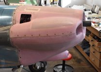
The cowling’s Mil-Spec quarter-turn fasteners are installed now. Still need to add the various locking elements. These quarter-turn fasteners are equivalent to Skybolts, the chief differences being that I had to make my own mounting strips and Mil-Spec seems to be out of business now. I started with an RV-4 kit for these but didn’t use them on the sides, deciding instead to use nutplates and screws. I have a number of spares now in case of an issue. I inventoried the parts and there’s plenty left for the sides, I I decide to change to them there.
Making my own mounting strips for the quarter-turn fasteners was a good thing. Mine are more compact than Skybolts and lighter, both plusses for this little RV-3B. On the sides, I laid up some glass to make glass flanges.
Up to now I’d been using clecos in the screw holes. Today I drilled them out to #19 for the #8 screws. I used a #19 reamer in the #30 holes and this worked perfectly. I got smooth accurate holes.
When I tried inserting the screws, I learned that two of the #8 nutplates had mysteriously shrunk down to #6. Probably I’d gotten them mixed up in the bins years ago. That gave me some practice removing rivets and installing new ones.
With AN525-7 screws and thin nylon washers, the cowl is finally secure. It lines up nicely with the cowl tool off, and I’m ready to move on. There’s some glasswork still needed before finishing, though.
Looking at these photos, I realized that I’d forgotten to install the nutplates and final drill for the front center attachments. Please let me know what else I missed! And yes, I added them today.
Dave