What's new
Van's Air Force

Don't miss anything! Register now for full access to the definitive RV support community.

Metal found in oil screen

Bavafa

Well Known Member
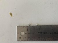
I did a oil change today and found this metal in the oil screen. The engine now has about 42 hours on it and the metall is not ferrous, look to be brass but can't say for sure.

Any thoughts as what this could be?

Edit: when you look at the picture up close, one side is serrated and rather uniformly and the other side is smooth.
 

Attachments

  • Metal shaving.jpg
    Metal shaving.jpg
    342.3 KB · Views: 464
Last edited:
Looks like drilling swarf. Send the picture to the company that built the engine, you must still be in warranty at 42 hours? Oil screen = sump scavenge finger filter? Is this the first time you have pulled that filter? The chunks are large, if something non-ferrous was breaking down it is difficult to imagine how so few lumps so big could come off without many more being present.
Pete

+1 for drill swarf from poor cleanliness prior to or at assembly.
 
If this is a Lycoming built engine, you can send the material to them for analysis at no charge. Here is the Lycoming service instruction regarding metal in the oil.
 

Attachments

  • SB480F Oil ServicingMetallic Solids Identification After Oil Servicing and Associated Corrective Act
    657.8 KB · Views: 899
+1 for drill swarf from poor cleanliness prior to or at assembly.
+1 on drilling debris.

The cleanliness issue would extend to the oil cooler and lines, if not adequately protected during airplane construction. It is also possible that the contamination got into an engine port during construction.
 
OMG what a fantastic repository of information this forum is! I’ve never even heard or seen the word “swarf” used in conversation.
 
Thank you everyone for chiming in. The engine is IO390-EXP119 and I have already sent a pix to Jeff @ Lycoming. I do agree that it looks like drill swarf and it was in the finger screen.
 
Swarf

Swarf? Everyone knows what that is. Let's see, there was Doc, Sneezy, Grumpy, Bashful...
 
Before I was a nurse, I was a machinist for 15 years. I agree 100%. Doesn't look like anything that could come from inside the engine. Had to be left over from mfg. process. A chip like that is either from drilling, a lathe, or milling machine.
 
Before I was a nurse, I was a machinist for 15 years. I agree 100%. Doesn't look like anything that could come from inside the engine. Had to be left over from mfg. process. A chip like that is either from drilling, a lathe, or milling machine.

I spoke to Lycoming and they believe the same, thinking it is from one of the internal port in the crank case that was left uncleaned. Nevertheless I am sending it in to be analyzed.
 
You'd think for a company which has been building the same basic engine for three quarters of a century, they'd have their processes down pat. But apparently not.
 
You'd think for a company which has been building the same basic engine for three quarters of a century, they'd have their processes down pat. But apparently not.

Alas! There's no such thing as perfection.

But we can try!
 
swarf

Looks like it could be drill shavings from installing a baffle kit, any chance the breather port was left uncapped during this process? I found the same in the cylinders of my HIO-360 when I tore it apart for inspection. In that case, the sparkplug openings were left unplugged.
 
Looks like it could be drill shavings from installing a baffle kit, any chance the breather port was left uncapped during this process? I found the same in the cylinders of my HIO-360 when I tore it apart for inspection. In that case, the sparkplug openings were left unplugged.

A shaving of that size and shape simply can't make it from the combusion chamber to the oil pan at least not while maintining it's shape. Something similar to what the OP posted must have come from machining inside the case, most likely from the oil gallery. If it came from the gun drilled holes in the crank, it would have been magnetic.

A shaving of that size and shape could not have come from the baffling. You won't get that size or shape from drilling 1/8" holes through .032 aluminum.

Larry
 
Last edited:
A shaving of that size and shape simply can't make it from the combusion chamber to the oil pan at least not while maintining it's shape. Something similar to what the OP posted must have come from machining inside the case, most likely from the oil gallery. If it came from the gun drilled holes in the crank, it would have been magnetic.

A shaving of that size and shape could not have come from the baffling. You won't get that size or shape from drilling 1/8" holes through .032 aluminum.

Larry
Agreed Larry. Not only I have been very careful with covering all the openings in the engine area (breather tube) the baffles on a 14 comes predrilled, other than the holes for the cooling tubes which were drilled off the engine.
 
Last edited:
My apologies for the drift

You'd think for a company which has been building the same basic engine for three quarters of a century, they'd have their processes down pat. But apparently not.

Sorry but you made me think of something I haven't thought about in many decades. Pulling up some ancient memories so hopefully I still remember the details.

The design and subsequent fabrication of the main injector assembly(ies) on the Space Shuttle Main Engines was a true marvel. A picture is attached from my old orientation manual. Liquid Oxygen is injected through the center of each of the 525 coax injector elements. Very cold (previously liquid hydrogen) and some steam are injected through the concentric outer part. The baseplate is rigi-mesh a gas permeable base to allow the H2 to come through and actively cool that area. Each post was friction welded into the base by spinning it up a few 10,000 rpms and pressing it into position. As mentioned, the assembly is as impressive as the design.

Removing machining chips was critical. Any blockage would not allow fuel/coolant flow and could cause a local hot spot -> damage if not potential catastrophe. There are three similar injector assemblies on each engine. A lot of government research money was spent on an x axis, y degree of freedom, z degree of motion machine that would shack the assemblies and assembled power head in all directions at varying frequencies to extract the various machining debris. Didn't work so well and some very expensive engines suffered damage.

So, the technicians went back to rolling these multi-million dollar assemblies around the asphalt parking lot on a rigid steel cart which had the rubber removed from the wheels. Problem solved, again.

Lycoming might have great procedures but poor execution or lack of QC and the results aren't guaranteed. Success is all about people at every level. Again, sorry for the drift (my new superpower) but it is relevant to the quote at least. Cheers boys.
 

Attachments

  • SSME main injector.jpg
    SSME main injector.jpg
    1.3 MB · Views: 79
Back
Top