Draker
Well Known Member
After months of agonizing and tweaking, I'm starting to get serious on a panel layout. So exciting! I figured before I get the chainsaw out, why not let hundreds of years of combined VAF experience loose to roast/critique it... likely there's something I didn't think of, or a better way.
(all images click through to larger ones)
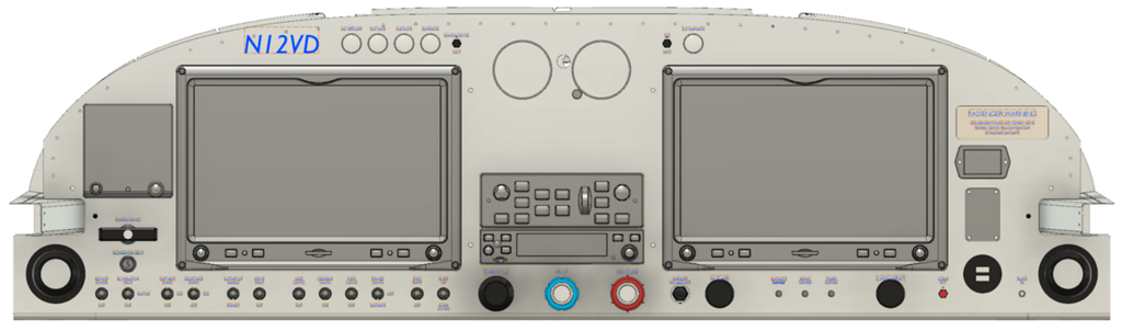
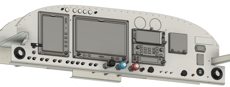
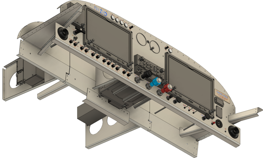
FRONT VIEW
This is an all-Garmin panel featuring two side-by-side GDU460 units. G5 backup display on the left. Center stack contains GTR 200B com radio and GMC 507 autopilot controller. The blank space is set aside for a potential (far future) IFR GTN 650. Above the blank area are backup airspeed and altimeter steam gauges.
I plan to use Van's 1" extended height panel--a single piece that extends from side skin to side skin, instead of the removable "ears", for the 1-1/4" air vents.
I could not find a pleasing way to fit pilot and passenger headset+LEMO jacks yet, so I may choose to hang small brackets underneath the panel for this purpose or go with jacks in the armrests.
Hobbs meter and ELT control over on the passenger side.
Under the G5 is a parking brake pull handle, and under that a single 5A circuit breaker protecting the alternator field supply circuit. The remainder of the aircraft's electrical circuit protection will consist of four 8-circuit ATO blade fuse blocks mounted on the sub-panel.
Very early draft of data interconnect plan, wiring harness, and wiring diagrams here.
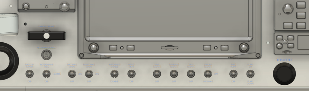
SWITCHES
Standard bat style toggle switches (from left to right):
PASSENGER SIDE
Self-explanatory. 3 separate dimmer circuits, pax PTT, Dual USB charger and stereo 3.5mm jack for music input
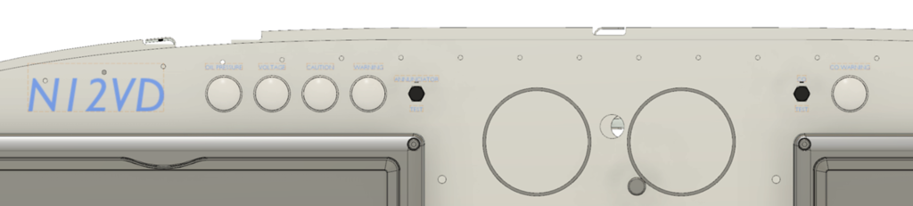
ANNUNCIATOR LIGHTS
Left side: Oil pressure, low voltage, master caution, master warning, and a switch to test flash them.
Right side: Carbon monoxide warning with test switch
This design leaves open the possibility of preserving the canopy release handle, if I choose to run it out to the panel.
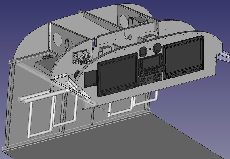
Due to the depth of the COM radio, a modification will need to be cut into the sub-panel. Also, as others have pointed out here in the past, this display configuration requires relocating the aft halves of the F-745 sub-panel ribs. Planning to attach the radio and AP brackets directly to those ribs.
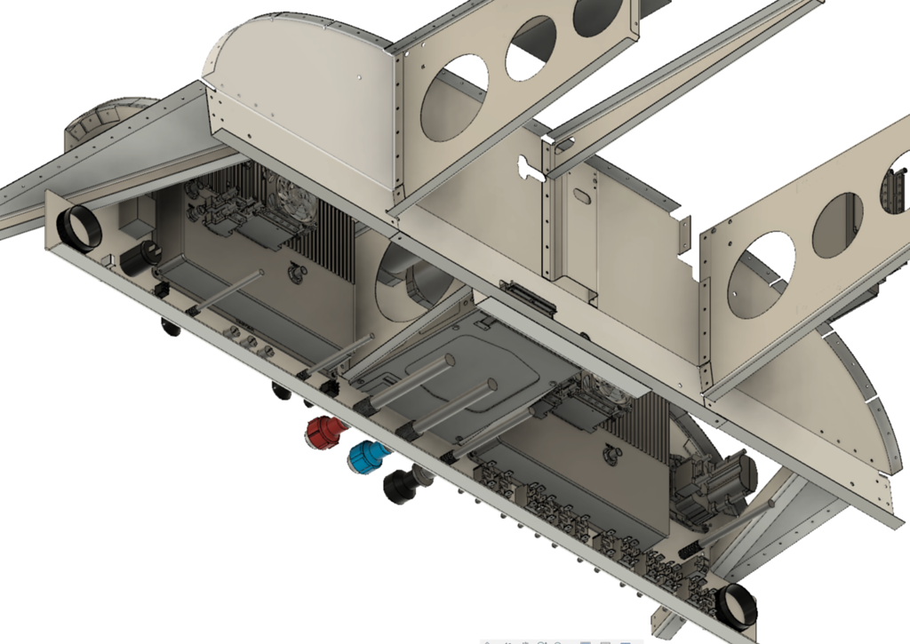
Clearance looks good for all pull cables and instrument depths, once the COM radio is accommodated.
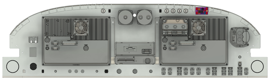
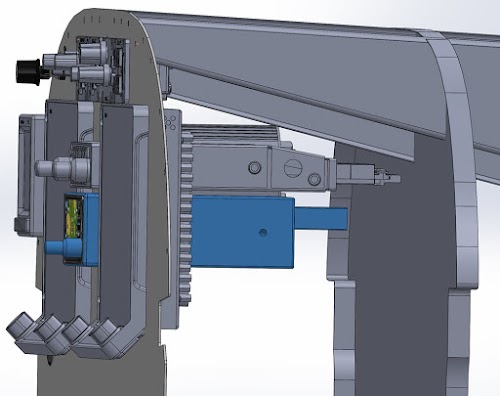
REAR VIEW
That's about it. Anyone have any suggestions or critiques?
Now all I have to do is mortgage the house...
(all images click through to larger ones)
FRONT VIEW
This is an all-Garmin panel featuring two side-by-side GDU460 units. G5 backup display on the left. Center stack contains GTR 200B com radio and GMC 507 autopilot controller. The blank space is set aside for a potential (far future) IFR GTN 650. Above the blank area are backup airspeed and altimeter steam gauges.
I plan to use Van's 1" extended height panel--a single piece that extends from side skin to side skin, instead of the removable "ears", for the 1-1/4" air vents.
I could not find a pleasing way to fit pilot and passenger headset+LEMO jacks yet, so I may choose to hang small brackets underneath the panel for this purpose or go with jacks in the armrests.
Hobbs meter and ELT control over on the passenger side.
Under the G5 is a parking brake pull handle, and under that a single 5A circuit breaker protecting the alternator field supply circuit. The remainder of the aircraft's electrical circuit protection will consist of four 8-circuit ATO blade fuse blocks mounted on the sub-panel.
Very early draft of data interconnect plan, wiring harness, and wiring diagrams here.
SWITCHES
Standard bat style toggle switches (from left to right):
- (SPST) IBBS Battery backup enable
- (DPDT) Combination Master / Alternator Field switch (Progressive OFF-ON-ON)
- (DPDT) Left Mag (OFF-ON-MOM)
- (DPDT) Right Mag (OFF-ON-MOM)
(Simultaneously hold both switches in the momentary up position to engage starter)
- (DPST) Autopilot servo enable
- (SPST) Pitot Heat
- (SPST) Nav (position) lights
- (SPST) Landing lights
- (SPST) Taxi lights
- (DPDT) Strobe/WigWag (Three position: Up is strobe, Down is WW, Center is off)
- (SPST) Boost Fuel Pump
- (SPDT) Flaps (MOM-OFF-ON, flap down is momentary)
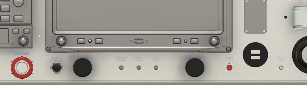
PASSENGER SIDE
Self-explanatory. 3 separate dimmer circuits, pax PTT, Dual USB charger and stereo 3.5mm jack for music input
ANNUNCIATOR LIGHTS
Left side: Oil pressure, low voltage, master caution, master warning, and a switch to test flash them.
Right side: Carbon monoxide warning with test switch
This design leaves open the possibility of preserving the canopy release handle, if I choose to run it out to the panel.
Due to the depth of the COM radio, a modification will need to be cut into the sub-panel. Also, as others have pointed out here in the past, this display configuration requires relocating the aft halves of the F-745 sub-panel ribs. Planning to attach the radio and AP brackets directly to those ribs.
Clearance looks good for all pull cables and instrument depths, once the COM radio is accommodated.
REAR VIEW
That's about it. Anyone have any suggestions or critiques?
Now all I have to do is mortgage the house...