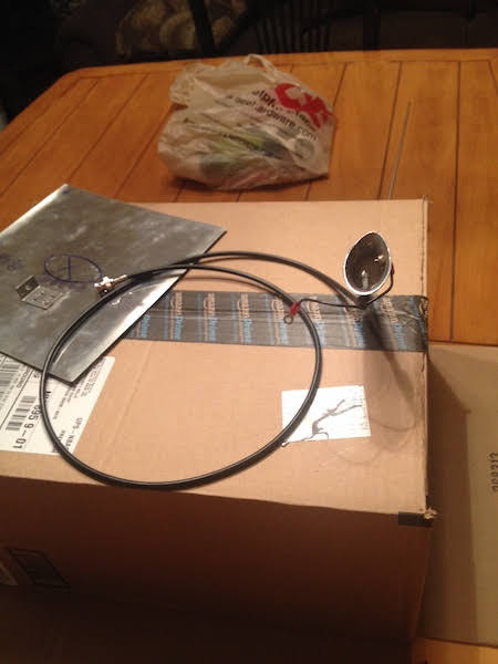
Jim Weir is Da man and contributes to Kit plane. He has written about this for decades. He had RST kits and still sells some things. He is a kit for $29 that is enough to make several antennas (VOR, LOC, COM, MB). Check the link below and the link to instructions. He spends a lot of time on VOR "Dipole").
http://www.rstengineering.com/rst/products/plasticplaneantenna/plasticplaneantenna.htm
Of course buying an antenna and bolting it on to the belly or turtle deck will be easy, have best performance and the drag I once calculated decades ago. I think we are talking 0.25 mph off top speed. Speed With Economy has numbers. This will be a compromise over a regular VHF mono-pole antenna bolted to the belly or turtle deck with a solid large ground plane which is about 23" inches in all directions. Not discouraging you.
Yep you are right a flat copper tape strip is better than thin wire, so I read like you. I do wounder how much "bandwidth" you are loosing. Voice AM (which is what we are doing) is not Hi-Fi. However since 3M makes sticky back copper tape it is kind of a no brain'er.
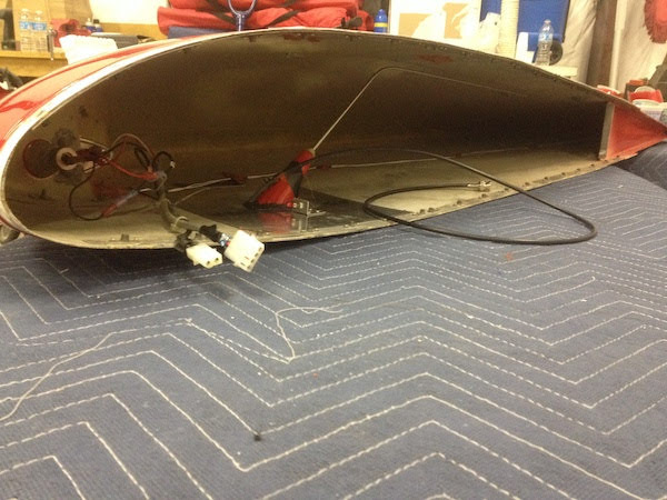
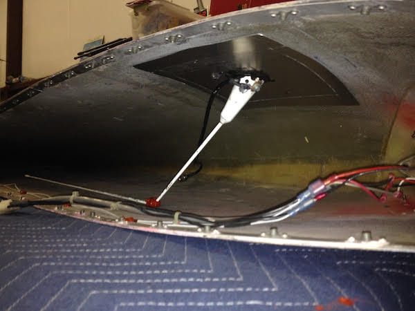
The RV-4 (which I flew a bunch but with belly antenna) has a tip over canopy. I can picture the challenge. I'm building a RV-7 slider so putting the antenna in the fixed front windscreen is easier, but the front bow might cause some dead spots. The better canopy is the tip up and using the glare shield as a ground plane. I like a strong radio, so I am going with a VHF antenna on belly.
You will have to terminate the strip and transition to 50 ohm coaxial. It will be an END FED (unbalanced) antenna and requires a ground plane. You will have to bring the feed line to the hinge line, into cockpit and run to your radio, no big deal. You have the cockpit edge longeron to run the coaxial under. The ground plane will be a creative exercise and challenge. You could ground it to the metal skirt around the back of the canopy but really want to tie it to fuselage turtle deck (ground). Also you may be grounding the canopy frame. Not sure what that will do. It could be goodness! It may be possible when you close the canopy you have a ground contact that grounds the skirt to the turtle deck>

Running the antenna over the canopy in the middle near the roll bar may cause some dead directions but you won't know until you try. It should work over 270 degree arc from front to back and off right hand side. I don't think it is worse than the buried antenna in one wing tip idea. Everyone says the wing tip antenna "works". By "work" they mean they can talk to the tower in the pattern, but forget getting out 10-20 miles at low altitude.
Find a HAM operator near you who has an antenna analyzer to test your antenna for SWR and Impedance. You understand about antenna length vs Freq. It is fun project, can be done cheap, you will learn a lot, even if you revert to a stick in the breeze. Again drag from one com antenna can't be measured it's so small but it is well under 1/2 mph. BTW I had a VOR dipole on the belly under the horizontal stab out in the breeze. When I did a few cross country races I took it off. If you are a speed demon you can take a com antenna off to race and use a handheld.