What's new
Van's Air Force

Don't miss anything! Register now for full access to the definitive RV support community.

Intercylinder Baffle Mod - Mixed Results

Toobuilder

Well Known Member
I've been thinking a lot about cooling for the last few years and I'm convinced the standard intercylinder baffles are a target of opportunity for improvement. Understanding that they are "good enough", I can't help but look at all the evidence that supports other, more effective cooling schemes. Even the lowly VW Beetle has a more elaborate/extensive shrouding scheme. Compared to aircraft, air cooled cars have very little volume to work with, so they need to use all the fin area they can. That's what my research tells me, anyway.

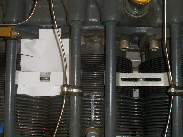
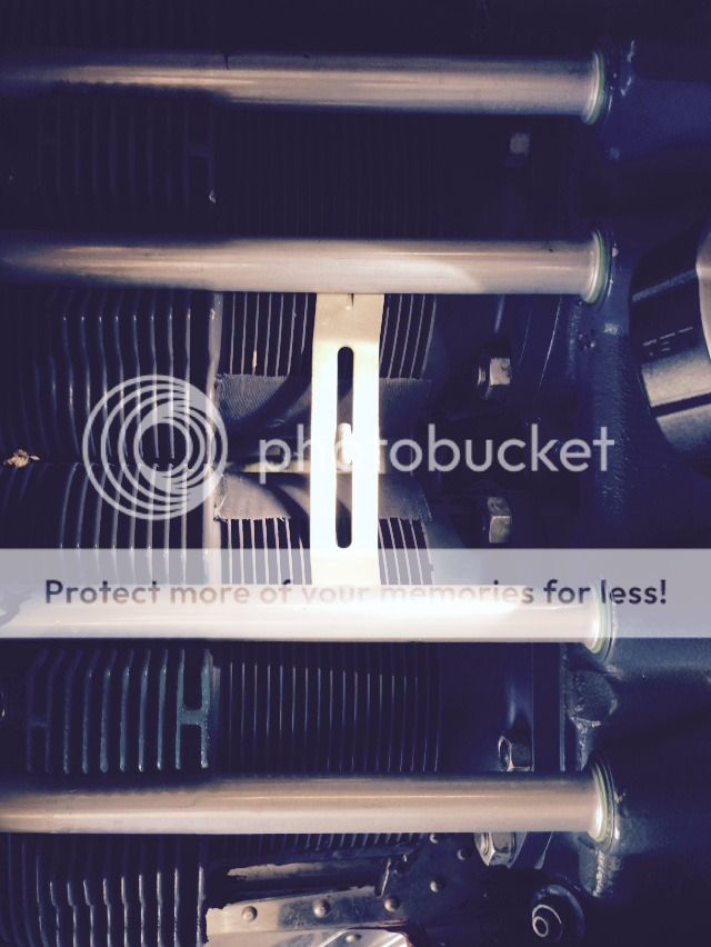
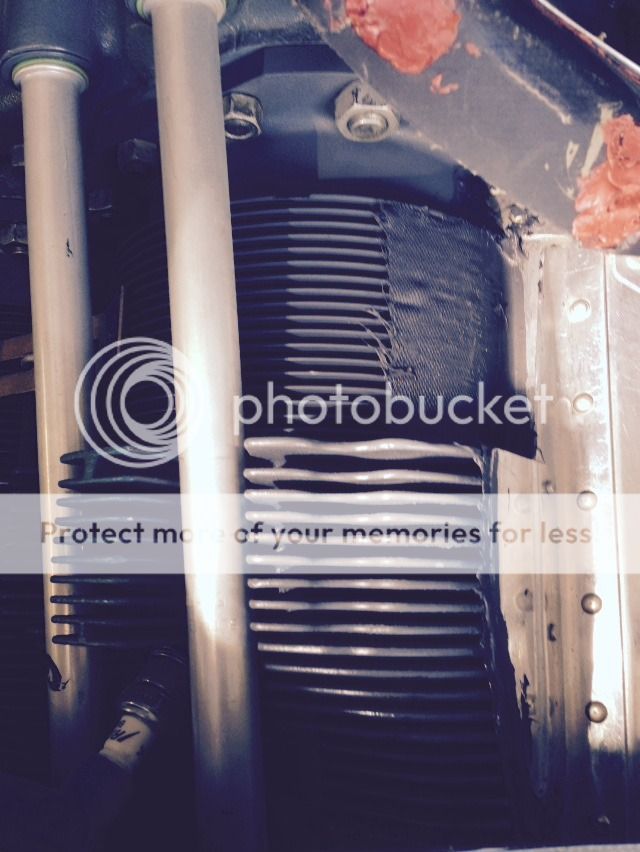
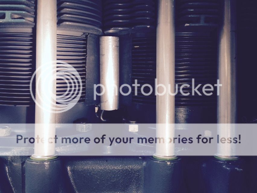
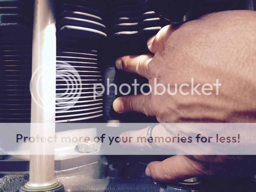
So with the goal of being able to reduce the overall air moving through the Rocket's cowl AND still cool effectively, I removed the standard Lycoming parts and fabricated cylinder shrouds. Following NACA research, these shrouds are large in initial volume and shrink down to the fins toward the exit. I also fabricated blocker plates which prevent any (and I mean ANY) air from going anywhere other than through the fins on the cylinders or heads.

ogxg81.jpg


2qsvsap.jpg


2s9x5ds.jpg


iofzid.jpg


Pressed for time and unsure of the results, I decided to only do one half of the engine (cyls 2,4,6). Flight test revealed a significant increase in temps on all three of these cylinders, roughly proportional to their normal order of imbalance (ie. 2 coolest, 6 warmer, 4 warmest). Discouraging at first, but comparing the other side (1,3,5) to my normal baseline, these all ran significantly cooler. In retrospect, I should have seen this coming. Given the choice between the torturous path through the cooling fins on one side, the available air took the easy way out through the seive like qualities of the stock baffles.

So, with a bunch of flying coming up in the next few weeks, I have removed the modification and restored the stock baffles - albeit with some careful tweaking and sealing to ensure minimal leakage. Flight test has revealed my cooling is slightly better than normal. Rather than discouragement, I'm back to the drawing boards for a more elegant, optimized cylinder shroud system. Next time I'll do both sides and report the results.
 
Last edited:
Nice job Michael, regardless of the unsatisfactory results.

It wouldn't surprise me if you made a set of these for the other side and saw all around improvement. I'd love to see that trial (hint, hint)...
 
There will be a "version 2.0", trust me. The next set will go "over" the pushrod tube to allow a more favorable convergent duct volume geometry. Right now, I'm limited by the angle between the bottom of the tube and the point where the shroud lays down on the cylinders (tangency). Without doing a compound curve, my initial plenum volume is pretty low and the shroud just follows the fins around for most of the barrel diameter. Not optimum, but was easy to fabricate for a quick test.

I did fabricate a complete set of the original configuration, but like many things I do I figured out a better solution late in the game.

Anyway, sucess or failure, it will be reported here for the collective good.
 
Mike, could you quantify "significant increase"?

My limited understanding of such things says the exits need careful shaping, somewhat like the baffle entrance seen here.

I think you're right about simply re-routing the air to the other side.
 
Mike, could you quantify "significant increase"?...

On my way home before the mod I collected temp data as a baseline. The condition was in stable cruise flight at 8500, LOP, 60 degrees OAT. The temps 1-6 were fairly typical for this flight condition and as follows:

328, 314, 354, 354, 340, 354.

The test flight revealed the following: (OAT= 67)

304, 318, 333, 381, 326, 375

The term "significant increase" may been hyperbole, but the misbehaving cylinders were much more difficult to keep under control in climb. #4 in particular settled on 425 quickly after takeoff. While this temp is not a big deal as a transient condition, I know that my local ambient temps are going to skyrocket in the next few weeks as we roll into summer.
 
Baffle design

I remember someone posting "optimal" upper and lower deck baffle gaps. My fallible memory seems to indicate that the optimal gap between the two baffles on a cylinder was greater in the upper deck than the lower deck. Can you compare these gaps somehow between the modified baffles and the other baffles, given that there is a flare around the push rod tubes on the modified baffles?
Interesting data points?.
 
I tried something similar a few years back, not as elegant as what Mike did, mine were simple flat plates blocking off the big gap between the cylinder fins on the top side----------I did not wrap the material around the fins.

Same result--------temps went up. I have no idea why this happened, as the theory seems sound, that forcing air to pass through the fins will lower temps, but theory be damned--------temps went up.

Here is a shot of the paper templates as I was working on the project----finished metal parts were identical.

P2070028.jpg


I do believe that the cylinder wrap setup like Mike has is the correct way to go, just need to find, and kill the bugs in the setup.
 
theory vs results

Back in my racing days, we went to the track to test theories. When we had the results, if they matched the theory we were good. If not, we believed the results and conjured up a new theory.
I think Michael is on to something here. But not everyone uses the same cowling, same engines, plenums (?). If it were all standardized it would be great, but them it wouldnt be experimental.
Keep it up Michael (and others) we all think outside the box.
Tom
 
Would rounded entry shapes help, or nozzle shapes at the exit? After all, there's air moving through there.

Dave
 
Great work Michael and I am surprised I am beating Dan to this comment.
I know it is more work but having cowl pressures before and after would help determine what is happening to overall mass flow.
 
Great work Michael and I am surprised I am beating Dan to this comment.
I know it is more work but having cowl pressures before and after would help determine what is happening to overall mass flow.

Ya see - Dan has us trained!!

Nice work Michael, but as you know, higher pressure will force more air through remaining "leaks" like oil coolers, alternator and mag blast tubes. Do you have those and/or a plenum? Average rise = 10F, but drop was -27F. Balancing the airflows should reduce the rise to a drop and give extra speed too (lower mass flow).

It is good to be reminded (of the balance), though, as I was standing just yesterday looking at that area and wondering . . .

Looking forward to your progress, maybe round the edges of the risers as air won't just go straight down.
 
I'm working with the asumption that most of the forward momentum of the incoming air (or is it better to say horizontal velocity?) is pretty low by the time it has made it past the front cylinders. I'm thinking most of the air in the upper cowl is essentially stagnant, but under ram pressure and looking for an easy way out. The rounded inlet I created by wrapping the pushrod tubes should be very inviting to air looking for an escape path. However, the shrouds do reduce volume quickly right down to fin height and remain that way for most of the circumference of the cylinder. Its this aspect that likely poses the most significant throttle to the system. With the heads retaining essentially the standard baffle configuration, the only other change is the fact that all other leaks were sealed - and that is always a good thing.

I believe that the cylinder wraps need more volume and yes, a better exit design.

Stay tuned!
 
A useful? reference to optimal cooling design

This topic is timely for me, as I am working on improving the cooling on my 9A. I am currently reworking my plenum and haven't started on inter-cylinder baffles yet, but am very interested in your results. In reading about the issue, I came across the link below which references five NACA reports on engine cooling and also discusses what the author considers the high points. I found it his summary informative and thought you might also be interested.

Rick

http://x-jets.com/a_cooling_efficiency.html
 
Excellent!

Thanks for posting that info Rick... That has given me a few more pieces of the puzzle.

And if you do decide to stick with the stock intercylinder baffles, make sure you spend a pit of time tweaking them to seal better. A bit of bending, speed tape and RTV goes a long way towards plugging unwanted holes. Best to do this before the engine is hung.
 
Last edited:
Glad you liked it!

Michael, Good advice about doing the intercylinder baffles before the engine is hung, but a little too late ... I'm just finishing up Phase 1.

Rick
 
i'm at the point of piddling some more with my baffling as well. I put new lycoming nitrided steel cylinders on just over 10 hours ago. Oil consumption seems to have stabilized and I seem to run about 20-30 degrees hotter than my previous chrome cylinders that the rings never seated on.
When I put the new cylinders on I also added some silicone baffle wraps A-La-DanH. I think at this point the higher temps have more to do with the baffle wrap than the newer cylinders.

The wrap between cylinders 1/3...
DF7E5308-5A76-4DAC-9EC3-FD80A3A5CB8E_zpsividxhm1.jpg


The wrap on the front of 1...
FAF600C8-8B7D-4D3C-9F9C-0E17CA2D0877_zpsqhjlhan6.jpg


I wondered if the square edges of the baffle wrap to fins cause some turbulence inhibiting air from entering the fins as well as less volume (140* top side exposure per Rick's post).

I'm thinking about adding a radius like this 1 inch aluminum tube between the cylinders and wrap the silicone baffle material over the top to help the air flow, it also exposes more area on top of the cylinder. From Rick's post my fins are .5 inch deep so my radius should be larger than .5, perhaps .75.
F94BF775-DA42-43BE-B120-3DED87432FC8_zpsox3hksie.jpg


0DB86510-8064-4FA0-A41A-4C285313D4B0_zpskzxrxczb.jpg


I'm also thinking of adding a radius at the front of the front cylinders and the rear of the rear cylinders with the tubing cut in half. I'm curious about using automotive heater hose/radiator hose with the right diameter, easier to source and shape than the aluminum tubing.
 
Made all my cylinder wraps from metal since they are parallel and easy to curl the ends.
Made all the head wraps with two layers of Bid wetted put with JB Weld for epoxy. Good to 550 degrees, can be trimmed and painted. Used an old cylinder for mold, covered it with packing tape.
If you're interested I can send you some photos.
 
The rounded inlets for the cylinders don't have to be that strong, so I am considering using 1100 from the rack at the hardware store. It rolls around a 5/8" dwell just fine. Maybe even 1/2" with spring back.
 
Everything I've seen indicates that a smooth inlet radius is paramount.

That said, I wonder just how much the cylinder fins contribute to cooling a lycoming? Clearly, they are important, but based on their small size and somewhat haphazard method of baffling, the heads are where the majority of cooling takes place.

My scheme for baffling the cylinder barrels is more to do with keeping the temps consistent around the circumference than as an overall increase in cooling capacity. I have no knowledge of any studies on the velocity of cooling air past the barrels, but intuitively, I'd think the top side is in relatively stagnant air, while the fins right near the stock intercylinder baffles sees a much higher velocity jet as the air shoots through that little gap. Seems to me this will pull the barrels out of round somewhat and that can't be good for ring sealing. Shrouding the barrels also make a convenient place to add the sealing baffles.
 
Back
Top