This has been an interesting discussion about wiring the B&C AVC1 Voltage Regulator. But I am still confused.
I was told by Van’s Support that the Instruction Sheets aren’t correct and that I should follow Service Letter 00034 instead.
I’m confused about:
1.) Where does the yellow wire from the Firewall Forward Harness connect to? I cannot find a label on this wire. I had assumed that this went to the Voltage Regulator.
2.) Is terminal #6 of the B&C Voltage Regulator to be connected to terminal # 4 and if so, then is the terminal to be cut off the P205 wire so that the yellow P3069 wire can be attached?
Looking at the RV-12 Wiring Diagram (i.e., my understanding that this is to be definitive source on all things wiring):
1.) The Firewall Forward Harness connector doesn’t show any yellow wires attached
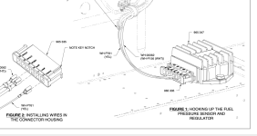
2.) Terminal # 6 of the B&C AVC1 Voltage Regulator shows a three inch long yellow P3069 wire attached. But this wire doesn’t connect to anything else.
Regarding Page 46-19 revision 4, Figure 4 specifically calls out all the wires except for the EFIS wire on terminal 5 as being for reference only. So, this isn’t an instruction on how to wire the other terminals.
Any assistance would be appreciated.
Brett H
Columbus, IN