When using internal lower cowl air as the source of filtered air, perhaps of greater concern than pressure is the temperature of that air, which is of course related. One would have to measure it to be sure but it would seem during summer months it could easily be 200F vrs 90-100F is using an external source. The cylinders are over 300 and the exhaust pipes over 1000 degrees, it is a warm environment. If anyone has measured forward lower cowl temperatures, it would be interesting information.
Really Eazy DECISION.
When in doubt open the ram air valve and have at least 1.5" over warm inner cowl air. Nice to use in icing. Don't use it the ram air unless you need it. Problem solved. A little dust will not cause that much damage if only for a few minuets.
Maybe a few "Extra Minutes on un-filtered air" (max HP) in a serious situation is better that no options at all. Who wants to get familiar with "terra firma"?
Why do RVr's increase compression ratio's and spend $$$$$ on speed mods that reduce the life of the engine for that extra edge when needed ? SECOND SUCKS that's why.
"Ram Air" is free..Use it when you need it. Close the valve when the air is dirty.
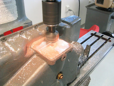
It may be interesting to note that 1/8" flange thickness on my ram air valve reduced the volumetric efficiency 8CFM (beveled and fixed) on a high end "FLOW BENCH" this week end. God forbid what 90 deg. turns and scatt tubing and filter off of the rear baffle does to air flow and volumetric efficiency.
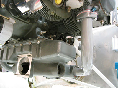
What about the relative air of 200 MPH in flight directly on the servo that's
6" from the prop blast. Not avialable in the inner plenum.
Something to ponder...Why does a NAS car engine (360cu) produce close to700 HP. on NON supercharged engines. LYCOMING 360 produces 180 HP @2700 rpm. Volumetric efficiency for one thing.
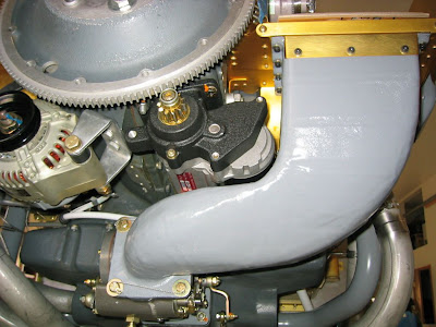
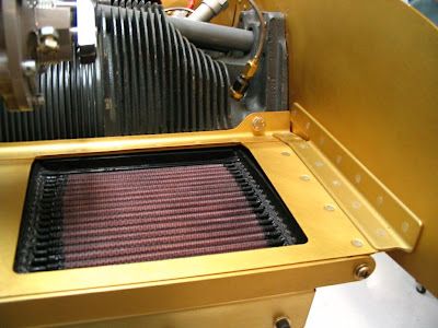
My ram air filter system Flowed 400CFM (bench flows at 400 CFM) and when it was swithed to K&N filerted air it Flowed 388 CFM (4%loss). This was not in a warm air environment but it is a consideration when comparing it to an inefficient system such as lots of turns and angles. Throw in a scatt tube and a poor filter then compare to the incremental loss (.5") of warm air in the cowl. These are hard numbers that can be verified at LY-CON engine rebuilders in Visalia.
I still have alot to learn, but I have built a Starduster II, an RV3, RV4, two RV8's A STEWART MUSTANG, and six restorations and have learned all kinds of things with each project.
30 Years of problem solving and having fun building Experimental Aircraft is just a start in this wonderful hobby.
I have been verifying results on LY-CON'S flow bench lately and it has allowed me to focus on just one part of the incremental approach to improving volumetric efficiency.
It's hard to beleive what a little head flow work/indexing the cam/roller llifters(Lycoming) electronic ignition/ and higher compression will do. Add all of the above incremental improvements and cold air induction/ram air and $$$. WOW -
Dave Ander's addressed the cooling and airframe drag issues and his improvements showed what his RV4 machine($65,000 NASA prize) is capable of. Eat's Harmond Rockets for lunch.
LY-CON (Visalia, Ca) has spent over 10 years developing their engine improvements and now have an STC on engine case "O" rings. They have thousands of hours of adding and removing material in Flow Bench Analysis. They finally digitized the results and consistently replicate the optimum head flowing. The Haws CNC is 5 axis and is really awesome.
I have been reading the reply's on the Ram Air and find alot of Pepper Tree Analysis with out flow bench analysis or real field comparisons. (apples to apples.)
There are so many variations in each experimantal induction system in the field that unless a standard system is addressed and compared to "say a Van's airbox" the observations are meaningless.
Early on, when I was flying my RV4 I remember a trip back from Prescot Az, with Dave Anders RV4. I was having trouble keeping up at 12,500 ft. My RV4 had a smooth bottom cowl and the filtered air was taken off the right rear baffle. He had electronic ignition and an angle valve and I didn"t. I figured that I would kick the RPM up a thousand. (and lie alot). Guess what, I slowed down. Volumetric efficiency!!! Solution...went to a Van"s lower cowl scoop. Problem solved. Figure that . Before I tried ram air.
How many stories and good times in 30 years.. I have already gone on to long.
Want to go fast---- talk to Dave Anders. He De Guru on Dat stuff.
Rod


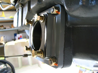
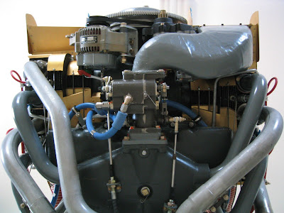
") I opted for the 2 valve deal and that's why there is a jump in MP when the ram air knob is pulled.
I opted for the 2 valve deal and that's why there is a jump in MP when the ram air knob is pulled.

