What's new
Van's Air Force

Don't miss anything! Register now for full access to the definitive RV support community.

wing painting fixtures

burgessbuilderMO13

Active Member
Gents
I am wondering what type of stand, jig or whatever you used to hold the wings while painting. My concern is supporting the wing safely, being able to rotate it etc. The problem is that the tip end of the wing has no place to firmly make an attachment without interfering with the painting of the tip area. Most rv wings have an open end to insert a support pipe or fixture, but not the 12. As the tip structure is riveted on and in place as a finished surface, it's kind of like painting yourself into a corner of a room.
Thanks
Dale L:)
 
Moment Connection

I will try to use a engine stand to make a moment connection the same way the aircraft holds the wing.

The problem is the moment connection to the floor for the stand


This should work fine with a little thinking.

Joe D

Gents
I am wondering what type of stand, jig or whatever you used to hold the wings while painting. My concern is supporting the wing safely, being able to rotate it etc. The problem is that the tip end of the wing has no place to firmly make an attachment without interfering with the painting of the tip area. Most rv wings have an open end to insert a support pipe or fixture, but not the 12. As the tip structure is riveted on and in place as a finished surface, it's kind of like painting yourself into a corner of a room.
Thanks
Dale L:)
 
Wingamajig

Gents
I am wondering what type of stand, jig or whatever you used to hold the wings while painting. My concern is supporting the wing safely, being able to rotate it etc. The problem is that the tip end of the wing has no place to firmly make an attachment without interfering with the painting of the tip area. Most rv wings have an open end to insert a support pipe or fixture, but not the 12. As the tip structure is riveted on and in place as a finished surface, it's kind of like painting yourself into a corner of a room.
Thanks
Dale L:)

Dale, I'm slowly getting around to painting my -12 in my garage, and had the same concerns. I came up with a "WINGAMAJIG" for doing just what you are concerned with. I still need to take some pictures, which I will post when I can...in essence, this is what I have done:
I had two Harbour Freight engine stands left over after using them for a rotisserie during fuselage build. I used one as the basis for the rotating jig--I removed the wheels from the engine stand, and replaced the rear (near the rotor) wheels with some 8- or 10-inch tires (Harbour Freight once again), and, using 2x10 lumber, attached about a 48" long deck to the lower frame of the engine stand. I then constructed a plywood plate (about 12 x 15" to the rotor portion of the stand (attached via four bolts), to which I then added a "sleeve" consisting of three layers of 3/4-inch plywood (with an added 1/4"inch inside to which the wing spar would conveniently slip, with two 1-1/2" holes placed such that, once the spar was placed in the plywood sleeve, I could use the steel spar pins to keep it in place. The sleeve measured about 3" thick, 9" wide, and 40-ish inches long. Near the far end (outboard) end of the sleeve, I attached a 12" diameter bearing wheel made with three layers of 3/4" plywood. (This wheel was about 3 or 4 inches from the wing root). Then, on the 2 x10 base I build on top of the bottom of the engine stand, I made a vertical stand which had two caster wheels at the appropriate height, such that the plywood wheel on the end of the sleeve was help up and could rotate on the two caster wheels, forming a nice, smooth bearing. I then further extended the bottom 2x10 deck with 10-foot 2x4s such that the end of the 2x4s was comfortably outboard of the CG of the wing+wingamajig. At the end of the 2x4s, I placed some swivel casters.
The whole thing then allows me to have the wing cantilevered out--no connections on the wingtip. The spar is elevated sufficiently to allow about a 270 degree rotation, using the metal tube handle on the end of the engine mount, with the every-45-degrees detents built into the shaft. The trailing edge of the wing won't quite clear the 2x4s (though they just may when I remove the flaperon.) Being mounted on fixed and swivelled wheels, I can grab the end of the wing and move the entire assembly out to my driveway for scrubbing/rinsing/alodine-ing, then push or pull the whole works into my garage-based paint booth for spraying. The entire length of the jig + wing is about 17 feet

This may be hard to visualize--I'll try to get some pics and video up soon.
 
When mine was painted, we attached the two wings together using the spar pins and then supported this assembly on two sawhorses across the spars. Made it very easy to roll the wings over. No need for any jigs whatsoever.
paint32.jpg
 
Last edited:
When mine was painted, we attached the two wings together using the spar pins and then supported this assembly on two sawhorses across the spars. Made it very easy to roll the wings over. No need for any jigs whatsoever.
paint32.jpg

Darn good idea!!!🚉🚁🚁
 
The shop that painted my aircraft left the wings on with no wing root gap seals when they painted. Looks fine, but corrosion isn't a big deal in Arizona so if it is in your area you probably want to remove them for painting.
 
Promised Wingamajig pics

Here are the promised pictures of my Wingamajig. As previously posted, such a jig can be easily replaced with a couple of saw horses and C clamps, IF you have plenty of space in your paint booth. Since my booth also my garage, I don't have that luxury, and thus resorted to this:

This is the rotor/sleeve assembly. The sleeve consists of two outside layers of plywood, approximately 9 x 45", and two inner plys of 3/4" and 1/4" cut to accept the tapered spar with a little wiggle room. The spar end attaches to the original engine mount rotor.

IMG_0264_zpsc8d81810.jpg


This is the wing root end of the rotor with 1-1/2" hole for the spar pin, and spring clip to hold it in place. the end of sleeve has corners trimmed to allow clearance for spraying the skins adjacent to the spar.

IMG_0266_zps61a24785.jpg


Additions to the Harbor Freight engine stand. 4-inch steel wheels replaced with 8" wheels to raise that end of the engine mount higher, to level the axis of rotation, and ease moving over the threshold of the garage/paint booth. Two 4-ft 2x10s, were bolted to the bottom cross-members of the engine stand, with a 2x8" skirt on the side. A 2x4 was placed on the back also, in anticipation of needing to add counterweight-turns out none needed.

IMG_0267_zpsaaad0e10.jpg


Two ten-foot 2x4s were added to assure no CG issues the 2x4s are slid inside and bolted to the 2x8 skirts and the angle between them adjusted to achieve the proper height of the wing above the jig's supporting 2x4s. Two 4" locking swivel casters were placed on the ends of the 2x4s.

IMG_0268_zps86b0b46a.jpg


Details of the main bearing--a sandwich of 2x4s between plywood was created to hold two 5" caster wheels. The end of the 2x4s is about 72" from the wing root--for this heavy-ended jig, no CG problems were seen. A much simpler design which gets the casters elevated to the proper height and angles is possible--this was just and evolutionary mistake that can be corrected in other builder's creative cycle.

IMG_0269_zpse38719ab.jpg


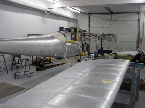
Start of the wing-sling to Wingamajig loading process--the sling is moved into position and the end of the wing spar inserted into the sleeve end. I removed the brass bushings from the wing spars to give easier clearance and to avoid any damage to the bushings.

IMG_0271_zps243cc63b.jpg


The end of the wing is then lifted and the spar shoved all the way into the sleeve: Both spar pins are then inserted and held in place with some spring clips (available from Home Depot Aerospace Dept). The wing sling is removed and we have a cantilevered wing stand! Rube Goldberg would be delighted!

IMG_0275_zps0a65cbc0.jpg


Using the handle on the end of the engine stand, the wing can be turned through about 270 degrees, and held in place at 45-degree increments by the pin in the engine stand rotor. Here is the wing in a horizontal/upside down configuration:

IMG_0276_zps3ca6da53.jpg


And here is a fuzzy picture of in rotated to its extreme for the trailing-edge down position:

IMG_0278_zps8d526066.jpg
 
Rob, if I correctly understand how your stand works, the wing-vertical position means the main spar will have to support the full weight of the wing in bending about its weak axis. If so, it would be worth checking with Vans to make sure that stresses in the spar will be OK in this configuration. In flight, the stub-spars provide fore and aft support to limit this mode of bending.
 
excellent point

Rob, if I correctly understand how your stand works, the wing-vertical position means the main spar will have to support the full weight of the wing in bending about its weak axis. If so, it would be worth checking with Vans to make sure that stresses in the spar will be OK in this configuration. In flight, the stub-spars provide fore and aft support to limit this mode of bending.

Indeed, it seems it could be a concern. Maybe Scott can comment. I would assume, however, that, in its worse position (vertical, the loading will be limited to the weight of the wing outboard of the rotator bearing--about 80 pounds, as opposed to the normal position load, in flight, where the loading will be about 1/2 the plane's gross weight times whatever the positive or negative G limit is.
 
Last edited:
Yes, I'm not saying it is a problem, only that it might be - especially if the wing `bounces' a bit in that position. The strength of the spar is vastly different depending on which way you bend it. It pays to be careful. :)
 
Yes, I'm not saying it is a problem, only that it might be - especially if the wing `bounces' a bit in that position. The strength of the spar is vastly different depending on which way you bend it. It pays to be careful. :)

Yup--says that, when I'm actually rolling the wingamajig around, I should do it with the wing horizontal, load-bearing position, and restrict the non-horizontal positioning to when flipping things around or painting at some angle. The dual-wing jigless approach described in a previous post would have the same type of stresses during the wing-flipping process.
 
Last edited:
The dual-wing jigless approach described in a previous post would have the same type of stresses during the wing-flipping process.

Possibly - wouldn't be a problem if the wingtip handholds were used to support the wing while turning it over. That's how the wings are handled normally - one person on each end. However, different story if the wings were left vertical with the tips unsupported.
 
Back
Top