What's new
Van's Air Force

Don't miss anything! Register now for full access to the definitive RV support community.

threaded fastener grip length

Blw2

Well Known Member
Read this article today
https://www.kitplanes.com/length-ma...anes+Weekly&utm_campaign=KP-Weekly-2023-09-19

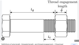
discussing selecting the correct length for screws, specifically re. grip length.

interesting report I think, but a little alarming as well. I'm no aircraft design expert, and it has been many years since I was heavily involved with machine design and the use and troubleshooting of threaded fasteners, but I do have quite a bit of experience in industrial settings.

...so I'm curious to know from you what I might be missing here.

The author prefaced by saying that most fasteners in an aircraft are in shear....but in my opinion didn't stress that condition as a foundation for his premise nearly enough...and all but I think one of the figures shows different applications that don't support the premise

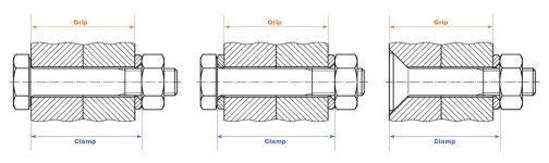
The point he makes does make a little sense if you are looking at the screw as if it's working like a simple loose shear pin... and perhaps there are many fasteners in a typical aircraft that are designed in such a way.... but for the most part this is not the case. A properly tightened screw or bolt joint is putting the screw into tension, that puts a clamping force on the parts. Several of the photos used shows this sort of arrangement...basically the screws are clamping the two parts together...and the shear load would be taken up by friction between the two parts.

Even at maximum load, the sides of the holes should never really be in contact with the screw's shank, in a properly designed joint. If such a joint ever gets to the point where the screw is taking the shear load, the joint has already at that point basically failed.

Instead, a threaded fastener should be selected to maximize the number of threads inside the grip length (or working zone) of the screw. This because most of the work is done by that portion.... (the smallest diameter and therefore the most "springy" part of it.) Especially in applications with high temperature swings, or higher impact loading, installing only one or two threads inside the working length puts a tremendous loading onto those few threads. I've seen quite a few failures from that sort of thing....
 
This is a long and well documented application. I didn't read the article but there was nothing in the quoted material that I questioned. I would question some of your statements as they contradict long validated principles. Speaking in general as there are always exceptions for engineered joints, my short response =

- It is a design goal to have threaded fasteners in shear vs tension whenever practical
- His point of "no threads in bearing" is basically never wrong
- The "clamping" load and joint friction are not a design consideration. For fasteners in critical shear applications, the torque value doesn't change (~50% of elastic range strain); however, the hole/fastener geometry becomes critical -> Interference fit (Hi-Lok-ish, some rivets), "zero" tolerance tapered fastener/hole, close tolerance fastener/hole geometry, etc..
- Fasteners in tension should counter-intuitively be torqued higher to ~90% of its elastic range.

A lot more could be said. There are enough books to fill libraries on this subject.

Most kits are designed to simplify the build process; one set of torque values, an assumption for a fairly high percentage of less-than-perfect rivets, etc.

The design margins in heavy industry are very large compared to aerospace. It's always good to question and learn but for proven designs, it's best to trust the OEM.

Build safe, Sir.
 
Last edited:
In aerospace, the goal is to never assume that friction carries any part of the load. And since fasteners in shear also have bending, we don't let the threads be inside the joint, since the smaller diameter is more likely to fail. Freemasm is entirely correct.

Dave
 
seems to me that a lot depends on the application, and that drives design decisions...and I suppose through combination of selecting screw size and grade, that sufficient strength and resilience could be had in only 1 thread in the grip....but boy oh boy you'd better make sure that nut doesn't bottom out before achieving proper tension!

In aerospace, the goal is to never assume that friction carries any part of the load. And since fasteners in shear also have bending, we don't let the threads be inside the joint, since the smaller diameter is more likely to fail. Freemasm is entirely correct.

Dave

So are you saying that holes are not designed/intended to be larger than the screws?

If I'm reading into that correctly, I kind of get that perhaps a design assumption might be that if a joint fails and the plates/parts do slip, that the screw can take the shear load
.... so a safety wired nut can't fall off the screw even if it's loose...and so the screw can't fall out...and the screw can continue to carry shear
but it would certainly not carry anywhere close to whatever the designed tension is
and besides....isn't the safety wire there to make sure that the nut can't become loose in the first place, so why would the screw ever carry direct shear loads?

anyway....ok, that (and the article) makes sense to me for applications such as maybe a clevis or pulley

But I'm not sure I'm buying that for flanges or bolt patterns holding together plates or parts. Holes are drilled oversize and the screws don't touch the sides of the holes to carry the load...and one of the primary points when designing a bolted joint is to use sufficient fasteners and sufficient sizes and grades so that the torque applied at installation tensions the screw properly (so that it sufficiently clamps and so that it can carry the working loads without ever yielding in tension)...and that usually results in a HUGE tensile force to hold the parts together. If the parts are slipping to impart a pure shear load onto the screw then it seems to me that something is lacking in the design...
 
seems to me that a lot depends on the application, and that drives design decisions...and I suppose through combination of selecting screw size and grade, that sufficient strength and resilience could be had in only 1 thread in the grip....but boy oh boy you'd better make sure that nut doesn't bottom out before achieving proper tension!


So are you saying that holes are not designed/intended to be larger than the screws?

If I'm reading into that correctly, I kind of get that perhaps a design assumption might be that if a joint fails and the plates/parts do slip, that the screw can take the shear load
.... so a safety wired nut can't fall off the screw even if it's loose...and so the screw can't fall out...and the screw can continue to carry shear
but it would certainly not carry anywhere close to whatever the designed tension is
and besides....isn't the safety wire there to make sure that the nut can't become loose in the first place, so why would the screw ever carry direct shear loads?

anyway....ok, that (and the article) makes sense to me for applications such as maybe a clevis or pulley

But I'm not sure I'm buying that for flanges or bolt patterns holding together plates or parts. Holes are drilled oversize and the screws don't touch the sides of the holes to carry the load...and one of the primary points when designing a bolted joint is to use sufficient fasteners and sufficient sizes and grades so that the torque applied at installation tensions the screw properly (so that it sufficiently clamps and so that it can carry the working loads without ever yielding in tension)...and that usually results in a HUGE tensile force to hold the parts together. If the parts are slipping to impart a pure shear load onto the screw then it seems to me that something is lacking in the design...

Wow. Further comments withheld, caught myself.

Some quick comments some of your statements

seems to me that a lot depends on the application, and that drives design decisions...and I suppose through combination of selecting screw size and grade, that sufficient strength and resilience could be had in only 1 thread in the grip....but boy oh boy you'd better make sure that nut doesn't bottom out before achieving proper tension!

What do you think the washer is for? It's secondary purpose to to protect the parent material from harm during torgueing. it's primary purpose to ensure the fastener doesn't "bottom out" while maintaining proper bearing engagement. The washer is not part of the load stack. An A&P can change fastener sizes, add an additional washer relative to drawing/spec to ensure a proper installation.

If I'm reading into that correctly, I kind of get that perhaps a design assumption might be that if a joint fails and the plates/parts do slip, that the screw can take the shear load


What is the purpose of the fastener other than to counter the (shear) load?

So are you saying that holes are not designed/intended to be larger than the screws?

See the previous post about criticality and resulting application (standard tolerance, zero tolerance, interference fit.

.... so a safety wired nut can't fall off the screw even if it's loose...and so the screw can't fall out...and the screw can continue to carry shear
but it would certainly not carry anywhere close to whatever the designed tension is
and besides....isn't the safety wire there to make sure that the nut can't become loose in the first place, so why would the screw ever carry direct shear loads?


Safety wire is not intended to maintain torque. It can't; but, rather to prevent further loss of preload through rotation; usually associated with relative movement via vibration or reversing loads. Have you noticed it's not specified for "non-blind" applications. A nut/bolt combo does not require it.

Going to assume you're not an engineer. The basis for a shear(ed joint) application comes down to two parameters only; the shear force and the area in bearing. After that, the material properties come into consideration. That's basically it. There's no consideration of surface finish of the mating parts (and resulting static friction), the torque and/or resulting clamping force, etc.

Want an example to consider? How much tensile force do you think a rivet is capable of? Go look at a 1097 rivet. IIRC, Lear Jets , modern Pipers, others, use them fairly exclusively in sheet metal apps.

Listen to any advice from Mr. Paule, the retired aero structures engineer from the republic of Boulder. For the foreseeable future, I would rigidly stick to the build plans, reference AC43-13, etc.

Build safe, Sir.
 
Last edited:
sheesh...such underlying hostility

I am only asking questions here, trying to understand why such a disparity in design considerations...

actually I am a Mechanical Engineer, with some experience in machine design and about equal years of experience in industrial maintenance reliability engineering which evolved quite a lot of NDT work and failure analysis.
but admittedly all that was quite a long time ago.....I'm doing different stuff in more recent years​
and no I am not an aerospace expert or a structural expert...
but I have looked at quite a few broken screws

you keep pointing to rivets..... but that's not the same thing. No threads in a rivet

The whole point I'm concerned about is the fact that work is done in the threaded section of the grip area because that's where the most resilience is in the screw....directly related to it being the smallest diameter typically, etc....
That is why it's generally accepted that a fastener's length is chosen to maximize the number of threads in the work portion (and likewise minimize the threads hanging outside the nut doing nothing but getting in the way...). this spreads the resilience over more threads.

I fully understand that there are bound to be applications counter to this. fasteners can most certainly be selected so that none of that matters....

But I will admit to having the feeling that this author was saying that every screw in an airplane should be sized for minimum (i.e one or maybe two threads) in the working length.... and that simply is not always true. I recon that probably wasn't the intent...but that was the impression I took from it....and I think there's could be a cautionary tale here that while perhaps true in some or even many places, it might not be everywhere!

and yeah, sheesh I'm NOT trying to say that folks should just willy nilly ignore the design plans and specs!....

one thing I'm pretty sure of is that almost nobody knows everything there is to know about a topic....even a structural engineer! so yeah, no harm in questioning things to get better understanding


so now, back on point.
If we are assuming that friction never carries the load, then is it generally true that screw sizes and grades are not selected selected so much based on torque value to yield strength for clamping force, but on diameter and shear strength?
....so basically structural screws in aircraft are acting more like clevis pins as opposed to cap screws or bolts?​
....and then by extension the required torque only needs to be enough to hold the screw in place, and not so much about holding tension in the screw to carry a tensile load to the parts together?

and also, so that that the screw can carry the shear, the hole sizes would be set much closer to the OD of the shank with little to no clearance (compared to a typical industrial application
an ANSI pipe flange for example uses a 5/8 inch hole for a 1/2 inch screw
 
Thank you^^^^^

I caught myself, too. Thank you for saying some of the things that needed to be said…

Edit…comment reference to Freemasm post above.
 
Instead, a threaded fastener should be selected to maximize the number of threads inside the grip length (or working zone) of the screw. This because most of the work is done by that portion.... (the smallest diameter and therefore the most "springy" part of it.)

Blw2...I get the feeling that you are misunderstanding what is meant (in aerospace) by "grip length". What you would call the "shank length" is what aerospace calls the "grip length". We do not necessarily select the number of threads in engagement with our aerospace standard nut/bolt combinations. What we do is make sure that only smooth shank (grip) goes through the holes in the mating parts. This is done for maximum surface area contact between the hole and the bolt, and allow no stress concentrations due to threads in bearing. Because fasteners come in limited variations of grip length, we then use washers of various thickness to tune this engagement to make sure we have complete thread engagement in the nut, without bottoming out upon torquing.
 
so now, back on point.
If we are assuming that friction never carries the load, then is it generally true that screw sizes and grades are not selected so much based on torque value to yield strength for clamping force, but on diameter and shear strength?

Generally, yes, as others have already stated. There are some engineered exceptions. There are even a few friction clamp applications, like engine torque transmission to a wood propeller hub. But again, generally speaking...

...and then by extension the required torque only needs to be enough to hold the screw in place, and not so much about holding tension in the screw to carry a tensile load to the parts together?

The specified torque values for standard AN bolts do not significantly preload them.

..and also, so that that the screw can carry the shear, the hole sizes would be set much closer to the OD of the shank with little to no clearance (compared to a typical industrial application

Correct. AN bolts are a few thousands undersize to they can be a firm push fit in the specified hole diameter. NAS shear bolts are slightly larger to reduce that clearance to near nothing. Sloppy holes are generally not acceptable.
 
"caught myself". I don't know what that means....

Blw2...I get the feeling that you are misunderstanding what is meant (in aerospace) by "grip length". What you would call the "shank length" is what aerospace calls the "grip length". We do not necessarily select the number of threads in engagement with our aerospace standard nut/bolt combinations. What we do is make sure that only smooth shank (grip) goes through the holes in the mating parts. This is done for maximum surface area contact between the hole and the bolt, and allow no stress concentrations due to threads in bearing. Because fasteners come in limited variations of grip length, we then use washers of various thickness to tune this engagement to make sure we have complete thread engagement in the nut, without bottoming out upon torqueing.

Yes, perhaps there is a slight difference in definition here!
it always comes down to semantics, right?....

Grip length is the distance between the bottom of the screw's head and the bottom of the nut. It's the length of the fastener put into tension by torqueing it (...well actually the tension tapers off up into the first few threads inside the nut (I forget exactly how many maybe 2-3 carry most of the load, depending on grades, etc.). That is the whole reason why torque values are set....to get a specific tension set in the fastener....

I understand that y'all all are talking about "grip length" as using the shank as a bearing surface to resist the shear. So that the entire length within the joined parts is not threaded.

Unless the hole is a tight friction fit against the fastener, I contend that the joint has outright failed if that ever happens. I mean, have the parts have moved away from their intended locations at that point?

and the thing is, in order to get a properly tensioned screw (in the world of industrial machinery, structures, etc... anyway) you usually want a lot more than just one or so threads that would be covered by a washer or two to be in the grip length.

I've gotten the idea that at least in a general sense, AN fasteners are sized so that the stress riser from only one or a partial minor thread diameter in the "clamp" does not pose high enough stresses in the screw for the design working tensions...basically the screws are grossly oversized for tensile strength
...or maybe, this idea of no threads in the grip only applies to some aerospace applications where the screws can be oversized or are otherwise not in high shock or high thermal loading applications

I went online and dug up some generic images.... saw several that did refer to the shank length to be the grip length as you're saying ...but that is contrary to anything I remember ever seeing before.....from my perspective that seems like a more generic fastener property term, and has nothing to do with an actual joint design. I found one interesting image from a fastener company in the UK that differentiated between grip and clamp lengths. I also don't recall using those terms.
 

Attachments

  • grip length.jpg
    grip length.jpg
    29.9 KB · Views: 57
  • clamp vs grip.jpg
    clamp vs grip.jpg
    207.2 KB · Views: 46
Generally, yes, as others have already stated. There are some engineered exceptions. There are even a few friction clamp applications, like engine torque transmission to a wood propeller hub. But again, generally speaking...


The specified torque values for standard AN bolts do not significantly preload them.


Correct. AN bolts are a few thousands undersize to they can be a firm push fit in the specified hole diameter. NAS shear bolts are slightly larger to reduce that clearance to near nothing. Sloppy holes are generally not acceptable.

Thanks Dan. I'll look more closely at that preload vs torque spec value. That'll probably help my understanding!
 
I've slowly found time to read/skim through that NASA document, Thanks again for that)

I think this paragraph is key to the article in Kitplanes and to my question, and probably should have been stressed...because the premise is not true for all threaded applications. I'm sure even in aircraft. There are bound to be applications in the structure and most certainly in the engine and other areas that are not primarily shear loading....
it really just echo's the point that catpart made earlier

Shear Heads and Nuts
In the aerospace industry the general ground rule is to design
such that fasteners are primarily in shear rather than tension.
As a result, many boltheads and nuts are made about one-half
as thick as normal to save weight. These bolts and nuts are
referred to as shear bolts and shear nuts, and care must be
used in never specifying them for tension applications. The
torque table values must also be reduced to one-half for these
bolts and nuts.​
 
Back
Top