I have a 3-conductor shielded wire that has RS-232 TX, RX, and signal ground.
I have a 2-conductor shielded wire that has RS-232 TX and signal ground.
What's the best way of splicing these two together, leaving the RS-232 TX disconnected on the 3-conductor wire?
It is not clear what you end up with. Are you saying you will splice the RS-232 RX from the 3-conductor wire to the RS-232 TX wire of the 2-conductor wire and then connect signal ground to signal ground? Implying that the signal is originating on the 2-conductor wire and is read by the device connected to the 3-conductor wire. If I understood this correctly, then:
On each shielded wire assembly strip 4 to 6 inches of the outside insulation off and then cut the shielding back 1 to 3 inches. Then solder and heat shrink the desired wires together either end to end or parallel. You could also use the mentioned solder-splices (sometimes called environmental splices) to do a butt splice of the desired signal wires. Then take a length of scrap wire and jumper the outside shield areas, again with either direct soldering or two more solder splices. Sometimes solder splices come with a wire already in them to be used as shielded drains and that would suffice also. For protection, as a first step you could slide a long piece of large diameter heat shrink over the3-conductor wire up and away from the splice so it can be used over the splice when the work is done. Then there's always electrical tape (eek!) or spiral wrap. Try n. t get too bulky.
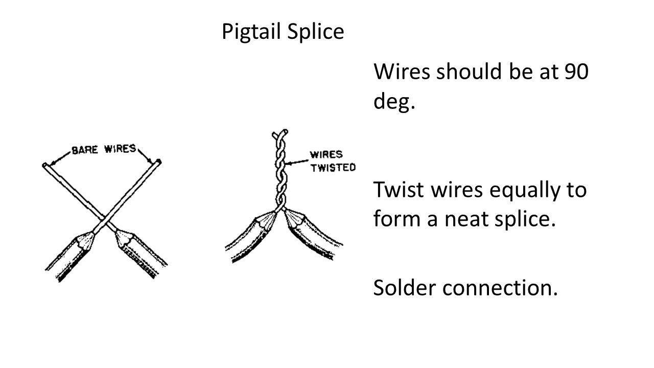
Parallel pigtail splicing can also be used but it is ugly. That's when two stripped wires are laid in the same direction so their ends are even and then soldered or solder spliced. Since there is now an open end heat shrink is applied after soldering and doesn't have to be put over one of the wires prior to soldering. Think of wire nuts in home wiring. Looks yuky but works. You end up with a kink in the wire run where the wires are brought together out of plane. Pigtailing is more common in situations like the Garmin bare wire cables for portable GPSs are connected to airframe wiring. Those little wires are sometimes 28 gauge or smaller and gnarly to twist together for an inline butt joint. It's easier to pigtail them. In your case pigtailing might allow soldering the shielding to each other since they will lie along side each other.
Kind of like this image except the stranded wires are laid parallel, not 90 degrees:
I would probably go with butt splicing via solder or solder sleeves myself.
With reference to your other questions, do not disconnect the shielding from either connector end of the existing runs because the rule of thumb is data wires should have their shielding grounded to the devices at each end to reduce interference. Your ends are already done properly so leave them alone. The short section you spliced and jumpered shouldn't be a problem unless that specific spot on the run is laying on top of a motor, strobe wire, power supply or similar noisy device.
As far as tying off the unused wire, industry practice is to put a short piece of heat shrink over the cut end and shrink it down so it is obvious the wire is unused and didn't get cut or pulled out of a connector. The next guy can tell it was intentional. After shrinking the heat shrink I usually pinch it with my fingers while it is still warm to cap it off. I then take and bend the wire back the way it came about an inch and zip tie it to the harness.
What devices are the ends connected to? Transponder? GDU? GPS? etc...
Here are some good videos courtesy of SteinAir in case you want a review of the standard handling of shielding:
https://www.youtube.com/results?search_query=steinair+shielded+wire