

In the past we've not posted a recommended schematic for wiring the components of our EFI systems in aircraft as it seemed everyone had their own preferences and ideas. Now, we're receiving more calls for recommendations so here's a schematic which some may find useful.
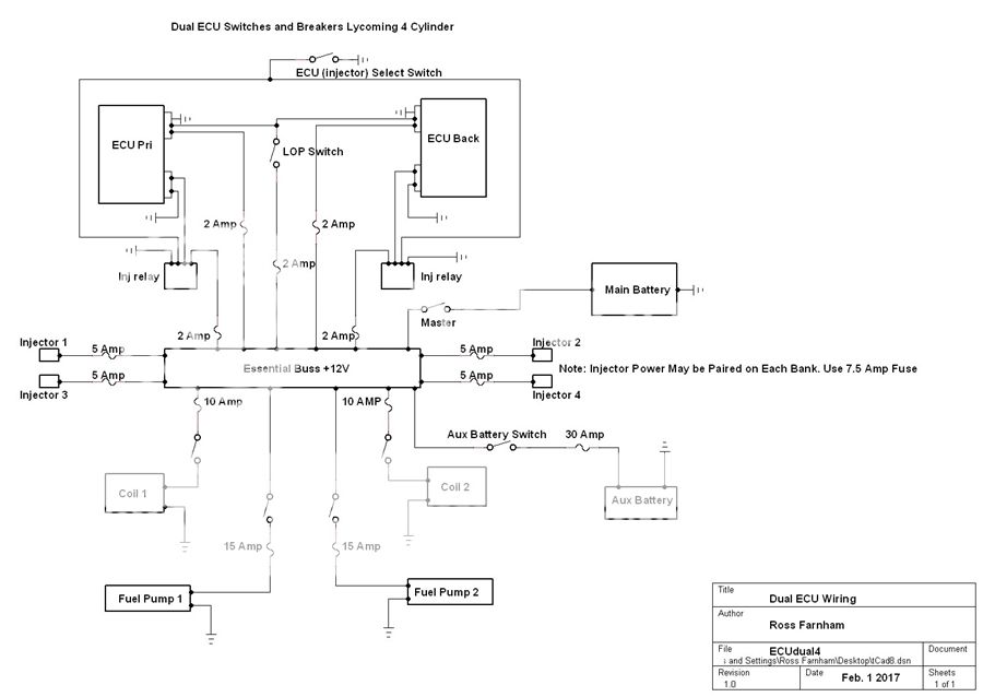
Notice there are two independent batteries and a fuse/ breaker/ switch for each fuel pump. There are also separate grounds for each device and separate switches for each important component.
There are no diodes.
There are no unfused main power wires feeding the essential bus.
We never recommend stacking grounds.
We never recommend critical components be tied to other component power switches or grounds as this does not promote redundancy.
Pilot intervention is required for all switching. You may run both pumps at low altitude.
Both ECUs are always powered. Each ECU is always running one set of 4 plugs. We only switch the injector outputs and relay default (closed contacts, no power required to them) has the primary ECU running the injectors.

