"Crescent" dimensions
Jay,
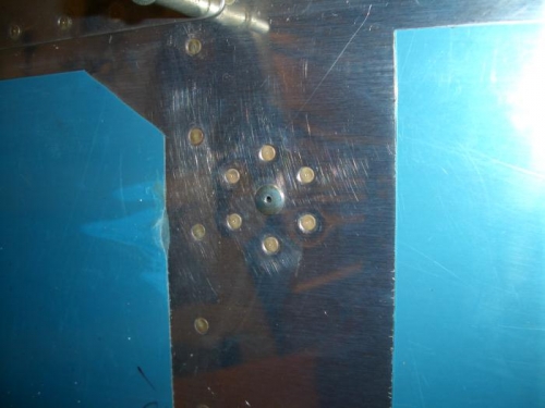
I used paper hole re-inforcements cut in half--you know, the kind you buy at the Office Depot that we used to use in the last century when you accidentally pulled a sheet out of a three-ring binder and tore the holes...back in the days when we were using white out on the computer screen
")
. I simply stuck 'em to the fuselage ahead of my originally flush ports.
If you suspect fast, put the "crescent" behind the static port. My data showed a nominal 1/2 MPH bias per layer. You could run a quick evaluation by making a quick known power run at say 4K, landing, sticking on four layers or so, and the repeating the speed run under similar conditions and noting any delta...then you can decide if its worth testing further to quantify. If you have good corrected speed data for your current static configuration, then you can skip the first step.
If you decide you want to peel the onion back farther, drop me an e-mail and I'll share a spread sheet that will do the math with your GPS speed run and ground test data. To use it, you'll need to know the instrument error for your altimeter (that may be available from a pitot/static check or on the 8130 that came from the instrument shop with the altimeter if it's a conventional type) and your airspeed indicator instrument error (that can be determined by building a simple manometer--google "checking your airspeed error" or something similar to pull up some good advice on how to go about this). Bottom line is that you have to have instrument error data before you flight test. If you've got an EFIS, it's likely the airspeed error is negligible. If you do have an EFIS, be careful with ground testing--improperly applying pitot pressure can ruin the calibration on the transducers since most systems utilize pitot/static input as part of the attitude algorithm. Most manufacturer's publish guidance on how to conduct a pitot/static check that may provide some additional insight.
To flight test, standard 3 leg GPS airspeed runs at known power settings will suffice. The objective is to bias flow around the port tor reduce CAS and altitude errors as much as practical.
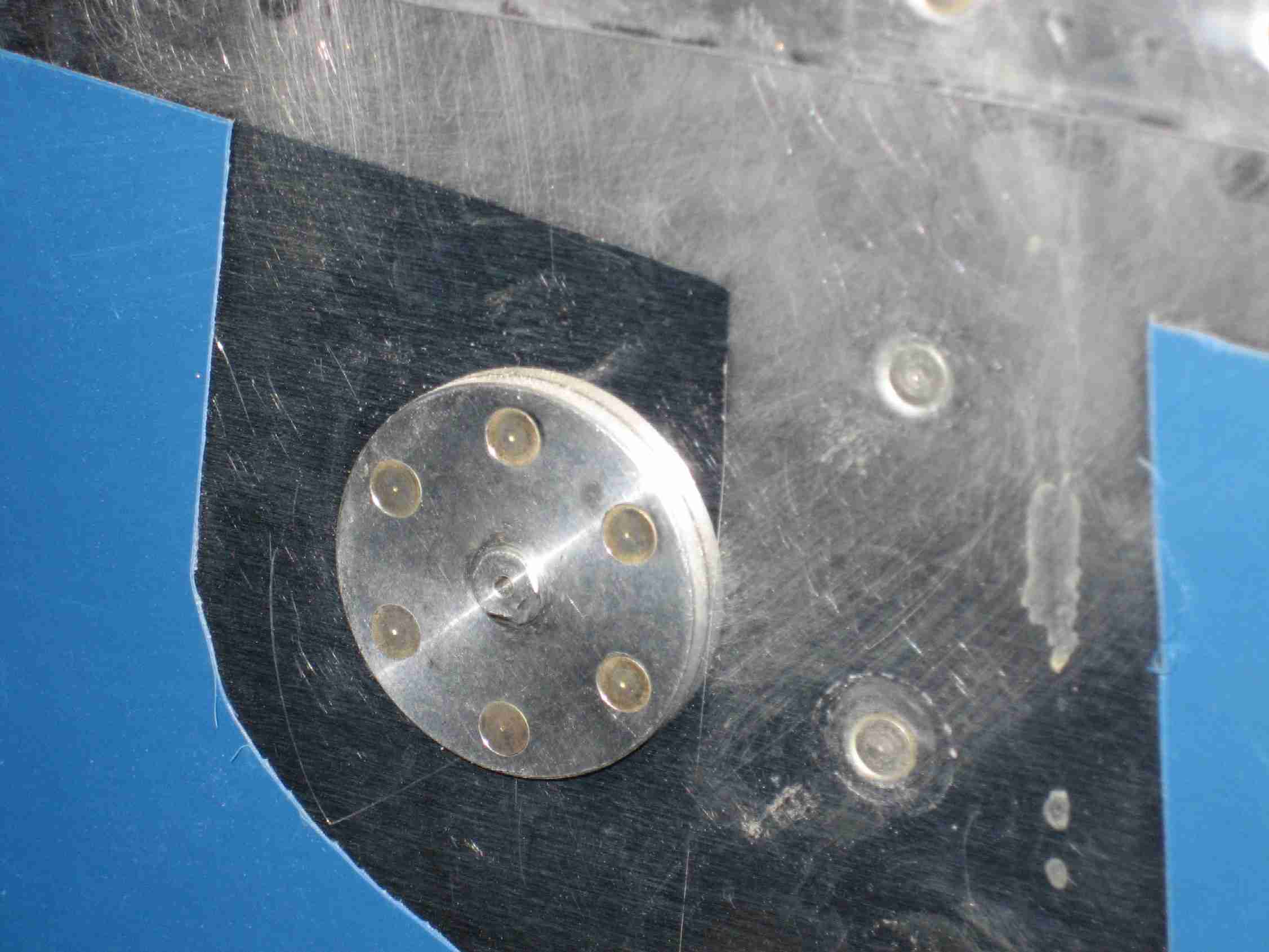
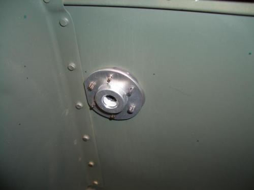
After quite a bit of testing, I determined simply offsetting the static source away from the fuse worked best (that's why the pop rivet design works well in RV's). I ended up retrofitting Cleveland ports which mimic the rivet dimensions as do the new safe air ports (based on a photo earlier in this thread). I also suspect a conventional Cessna-type port that stands proud of the fuselage would give good results as well.
Likely more info that you need, if so disregard. If you have any questions, don't hesitate to drop a line.
Good luck,
Vac