

Thanks to Tom Swearengen of TS-Flightlines, we now have all of the firewall forward fuel lines we needed to hook up our new TMX-IO320 in the RV-3! This was by no means a ?stock? installation (there is no such thing for an RV-3, or an experimental engine), and without a FWF kit, we were pretty much on our own to figure out how to make it work. Fortunately, we didn?t run into anything that couldn?t be covered with standard techniques and practices, so it was mostly a matter of figuring out good lengths, hose ends, and routings. I generally like to build my own fluid line when doing a ?custom? installation, because I can get the lengths exactly right by attaching one end, then measuring ?in place? to attach the other. I?ll do that with the oil lines for this plane, as they are fairly straightforward, but for the fuel lines, I wanted to try the newer style ?brown? sealed fire sleeve, and since we already had one such line that came with the engine it only made sense to make a matching set. (The engine came with two lines, one from the pump to the servo, the other from the servo to the flow divider. Unfortunately, we had to change the servo from a left-feed to a right-feed to make the mixture arm work right with the RV FAB, so the ?short? line was no longer appropriate)
Because the fuel injection system is not certified (Precision Silverhawk) on this engine, I was already in ?experimental? territory with the powerplant, so I decided to design and fabricate my own bracket and location for the fuel flow sensor, putting it between the Servo and Flow Divider, rather than further upstream in the ?airframe? part of the system. This has been shown to provide a more accurate measure of fuel flow than when the flow transducer is closer to the fuel pumps ? while not essential, it is ?nice?. I consulted with Mahlon at Mattituck about a good location for the ?Red Cube?, and he said that on certified aircraft, it is frequently put between the servo and the divider as well, so this made it more attractive. Of course, the fact that the RV-3 is so compact made it impossible to find a good place to put the ?red Cube? anywhere between the fuel selector and the engine driven pump made the decision easier as well. With the straight-pipe (non-cross-over) exhaust, the front of the oil sump was wide open, so I built a bracket from 4130 steel that mounted to two sump bolts and gave a very solid and straight mounting plate for the cube.

Once the flow transducer was in place, it was a simple matter to decide on the four total hoses we needed between the firewall and the flow divider, figure out a natural routing, and pick appropriate ends (straight, 45?s, 90?s, etc). To clear the throttle arm and linkage, Tom suggested a ?long drop? 90 degree fitting fabricated from stainless steel that has been used on similar installation, and after consultation with a couple of engine builders, this sounded like a good plan to me as well. I measured hose lengths for Tom using a piece of nylon static system tubing that seemed to like to bend at approximately the same radius as the fuel lines we were using, holding it up between the various end fittings, then measuring the resulting lengths. The line from the firewall to the engine-driven pump was made a little long to give it a little bit of an S-curve to allow for movement. In the pictures shown, I have not added final Adel clamps and rub-point restraints, so if you see a ?hey, that?s going to abrade!? spot, I probably already know about it. I generally run a fuel system with my hands touching the lines from end to end to find places that need restraint and/or protection.
Firewall to fuel pump:

Fuel Pump to Fuel Servo:

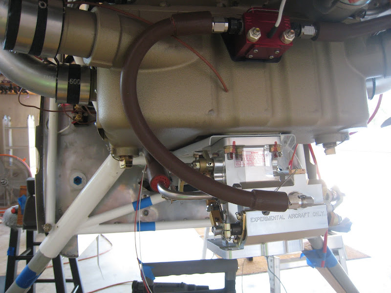
Servo to Flow Transducer and on to the Flow Divider (around the back of Cylinder #4):

You?ll notice that I took pains to caveat a few things about this being an ?experimental? installation on an ?experimental? engine. With those considerations comes the burden of understanding that there can always be surprises, and it will take some flight testing and rigorous inspection in the early days of the airplane?s life to make sure that we don?t have a vibration or wear problem. I doubt that we?ll be taking this Single-Engine airplane into conditions where the loss of that engine would be catastrophic until we have done a significant amount of diligent testing to confirm that our designs are satisfactory in this regard.
Because the fuel injection system is not certified (Precision Silverhawk) on this engine, I was already in ?experimental? territory with the powerplant, so I decided to design and fabricate my own bracket and location for the fuel flow sensor, putting it between the Servo and Flow Divider, rather than further upstream in the ?airframe? part of the system. This has been shown to provide a more accurate measure of fuel flow than when the flow transducer is closer to the fuel pumps ? while not essential, it is ?nice?. I consulted with Mahlon at Mattituck about a good location for the ?Red Cube?, and he said that on certified aircraft, it is frequently put between the servo and the divider as well, so this made it more attractive. Of course, the fact that the RV-3 is so compact made it impossible to find a good place to put the ?red Cube? anywhere between the fuel selector and the engine driven pump made the decision easier as well. With the straight-pipe (non-cross-over) exhaust, the front of the oil sump was wide open, so I built a bracket from 4130 steel that mounted to two sump bolts and gave a very solid and straight mounting plate for the cube.
Once the flow transducer was in place, it was a simple matter to decide on the four total hoses we needed between the firewall and the flow divider, figure out a natural routing, and pick appropriate ends (straight, 45?s, 90?s, etc). To clear the throttle arm and linkage, Tom suggested a ?long drop? 90 degree fitting fabricated from stainless steel that has been used on similar installation, and after consultation with a couple of engine builders, this sounded like a good plan to me as well. I measured hose lengths for Tom using a piece of nylon static system tubing that seemed to like to bend at approximately the same radius as the fuel lines we were using, holding it up between the various end fittings, then measuring the resulting lengths. The line from the firewall to the engine-driven pump was made a little long to give it a little bit of an S-curve to allow for movement. In the pictures shown, I have not added final Adel clamps and rub-point restraints, so if you see a ?hey, that?s going to abrade!? spot, I probably already know about it. I generally run a fuel system with my hands touching the lines from end to end to find places that need restraint and/or protection.
Firewall to fuel pump:
Fuel Pump to Fuel Servo:
Servo to Flow Transducer and on to the Flow Divider (around the back of Cylinder #4):
You?ll notice that I took pains to caveat a few things about this being an ?experimental? installation on an ?experimental? engine. With those considerations comes the burden of understanding that there can always be surprises, and it will take some flight testing and rigorous inspection in the early days of the airplane?s life to make sure that we don?t have a vibration or wear problem. I doubt that we?ll be taking this Single-Engine airplane into conditions where the loss of that engine would be catastrophic until we have done a significant amount of diligent testing to confirm that our designs are satisfactory in this regard.
")

