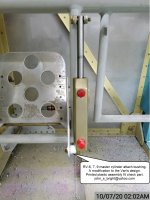
I've recently been working on wrapping up the fitting of the brake pedals to the rudder pedals. In the interest of reducing free play and wear, I opted for the single, long bolt instead of two shorter bolts for the brake pedals. I also wasn't satisfied with the bolt in single shear with a stack of washers as a spacer for the master cylinder to brake pedal attachment. I decided to make a custom stud:
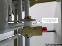
A closer view. Note this is my prototype, so I hadn't bothered to thread the portion of the stud which extends through the master cylinder:
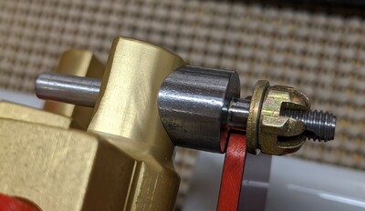
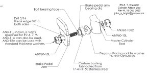
The stud and spacer are silver soldered together. The stud end going through the brake pedal tab will be use a castle nut (installed loosely) and cotter pin. The stud end going through the master cylinder will use a fiber locknut (installed tight). The contour of the little spacer is there to prevent rotation between the stud and master cylinder.
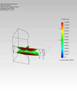
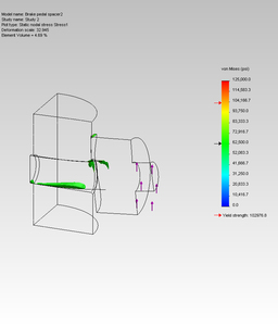
I did a bit of analysis to check and ensure the result was OK from a stress and deflection perspective. I am not privy to the design loads Van's used for their analysis, so in the interest of picking a value, I chose a load matching to the burst pressure of the 3003-O brake line tubing. Since this is a linear static analysis, loads below this (rather arbitrary) load will be proportionally less. Also, note that as a a linear static analysis, any stresses shown above yield will not be accurately reflected in the model. Clipping in these two screenshots is at .5Su.
Van's design - significant bending stress, >.015 deflection.
Modified design - reduced stresses, .0025 deflection.
I installed one of the pedals per Van's instructions and measured free play at the top edge of the pedal: ~1/8".
I then disassembled and reassembled with the long pivot bolt and this little custom stud, and again measured free play at the top edge of the pedal: ~1/32".
This post isn't intended to be controversial or suggest that anything is wrong with Van's design...just trying to share what I did in case anyone finds this useful. If anyone decides to duplicate the effort, I created a drawing which, hopefully, is useful.
A closer view. Note this is my prototype, so I hadn't bothered to thread the portion of the stud which extends through the master cylinder:
The stud and spacer are silver soldered together. The stud end going through the brake pedal tab will be use a castle nut (installed loosely) and cotter pin. The stud end going through the master cylinder will use a fiber locknut (installed tight). The contour of the little spacer is there to prevent rotation between the stud and master cylinder.
I did a bit of analysis to check and ensure the result was OK from a stress and deflection perspective. I am not privy to the design loads Van's used for their analysis, so in the interest of picking a value, I chose a load matching to the burst pressure of the 3003-O brake line tubing. Since this is a linear static analysis, loads below this (rather arbitrary) load will be proportionally less. Also, note that as a a linear static analysis, any stresses shown above yield will not be accurately reflected in the model. Clipping in these two screenshots is at .5Su.
Van's design - significant bending stress, >.015 deflection.
Modified design - reduced stresses, .0025 deflection.
I installed one of the pedals per Van's instructions and measured free play at the top edge of the pedal: ~1/8".
I then disassembled and reassembled with the long pivot bolt and this little custom stud, and again measured free play at the top edge of the pedal: ~1/32".
This post isn't intended to be controversial or suggest that anything is wrong with Van's design...just trying to share what I did in case anyone finds this useful. If anyone decides to duplicate the effort, I created a drawing which, hopefully, is useful.
Last edited: