Rallylancer122
Well Known Member
I'm retrofitting a pair of G5s into a completed plane. Was going to put the magnetometer in either the tailcone or wingtip. Problem is the plane has an old school Whelen incandescent strobe system. The single power supply is in the tailcone with wires run through the fuselage and out to the wingtips. Seems like every place I could conveniently run the canbus wire there's already a strobe wire.
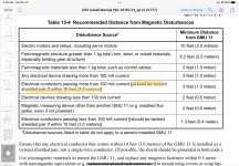
Sooo....how far away do I need to be from a strobe wire, practically speaking? The manual doesn't provide anything other than generic guidance on this. Just not sure how sensative that magnetometer is ( or I guess actually the canbus signal).
Sooo....how far away do I need to be from a strobe wire, practically speaking? The manual doesn't provide anything other than generic guidance on this. Just not sure how sensative that magnetometer is ( or I guess actually the canbus signal).
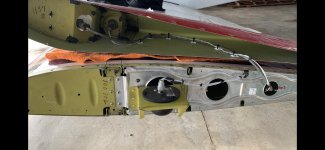
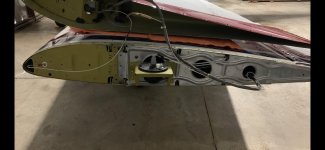
 Not only that but it was not secured and messy.