What's new
Van's Air Force

Don't miss anything! Register now for full access to the definitive RV support community.

Lower Cowl Contouring/Shaping vs a bump out

snoopyflys

Well Known Member
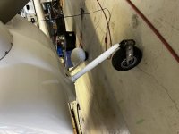
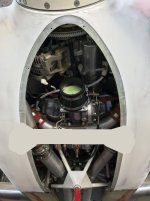
Now that I have my cowling fitted and close to being finished, I have a couple of concerns that may/may not happen once the engine settles. Right now, my Vetterman Trombone exhaust is about a 1/4 to 3/8” from the lower cowl. The Vetterman folks said this was ok would be nice if it was a little more. Second, I had to cut out a section to allow my horizontal induction mixture control to clear. So, rather than add a couple of bump outs, “Pimples”, on the lower cowl, I am considering going to the extreme by lowering the bottom center about an 1” to clear the exhaust and the mixture control. With that, are there any gotchas and tips I should be aware of before heading down this path with regard to cowl structural integrity or the what glass to use, etc?
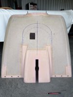
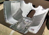
Here is a picture of what I have in mind. The “X” on the right is where the #2 exhaust tube is located and the square hole is where the mixture control linkage is located.
 

Attachments

  • IMG_2575.jpg
    IMG_2575.jpg
    427.7 KB · Views: 134
Obviously you want it to look nice. Just spend extra time analyzing the shape and that it is complimentary in appearance to the plane. Get others to take a look to. Sometimes we see mods that are just out of place and look weird.
 
Cowl

What is different that requires such a major modification?
Mine is a 7A (new gear), IO-360-M1B, Vetterman. No issues with controls or exhaust. I did install a few Antisplat heat shields to protect the cowl and fuel line.
 
The Difference….

I have an ECI XIO-360 with a ECI cold air sump which is a tad bit different than the standard lycoming or the popular Superior cold air sump. Secondly, the Trombone style exhaust (no longer available from Vetterman, at least for my config) has the #2 exhaust a little farther forward than usual. And I have the AFP “ Continental/Titan 4 Cylinder Cold Air Sump FM-150 Cable Bracket Kit ” which I had to rotate the throttle body 90 dregs to allow the controls to work correctly. So, just wondering if there are things to be aware of before I start hacking on the lower cowl.

Thanks,
 
Last edited:
So, just wondering if there are things to be aware of before I start hacking on the lower cowl.

The cowl is roughly rectangular where it attaches to the fuselage, but internal pressure tries to blow it out to a round shape. The top and the sides are well supported, but there's a significant gap in support across the bottom, specifically the span across the exhaust outlet. The result is very high loading of the fasteners or hinges on each side of the outlet, at "B" in the sketch. It's why the hinges break there.
.
 

Attachments

  • Cowl Pressure Shape.jpg
    Cowl Pressure Shape.jpg
    17.1 KB · Views: 75
Cowl

I have an ECI XIO-360 with a ECI cold air sump which is a tad bit different than the standard lycoming or the popular Superior cold air sump. Secondly, the Trombone style exhaust (no longer available from Vetterman, at least for my config) has the #2 exhaust a little farther forward than usual. And I have the AFP “ Continental/Titan 4 Cylinder Cold Air Sump FM-150 Cable Bracket Kit ” which I had to rotate the throttle body 90 dregs to allow the controls to work correctly. So, just wondering if there are things to be aware of before I start hacking on the lower cowl.

Thanks,

Ok. Now it's clear.
The area you outlined is honeycomb. The skin is pretty thin.
Dan would be the expert, but I would recommend a scarf joint. The honeycomb would be removed several inches away from the cut line. Clean it well and new material will bond to the outer skin. It doesn't need to have honeycomb replaced but the joint should be at least as thick as the non-honeycomb area of the cowl. Probably 6-8 layers. A mold would make it easier to achieve a symmetrical shape. A piece of pink construction foam is pretty easy to shape.
Maybe Dan will chime in with a better plan.
 
I did similar to make room for a custom air snorkel for my SDS system.

Some steps I followed:
#1 - attach a angle along the lower back edge of the cowl to preserve it's shape & spacing, drill for a series of #40 clekos to hold it on.
#2 - I defined the new contour by laying out a grid, glue 1"x1"x(cut to varying heights) foam blocks (pink or blue insulating foam bought at Home Depot) that would determine the depth of the new shape & be able to shape it evenly both sides. Than pored 2 part expanding polyurethane foam over the area to form the new shape. This took a number of small pores to cover all the area without making a big mess. Next using various rat tail files & sanding blocks, the polyurethane foam was sanded down to the pink marker foam blocks to final shape.
#3 - As I was not too caring how the inside surface came out, I covered over the new foam shape & flange edge areas with duct tape & applied wax mold release over it.
#4 - I layed by-directional fiberglass cloth over this, 2 layers overall, an additional layer inboard of the flange edges.
#5 - After curing, drill around the edge for #40 clekos, than popped the new fiberglass panel off with air pressure. Now you can clean off the outer edges of the foam so you can cut out the unwanted sections of the lower cowling.
#6 - Use a dremel tool to remove back the inner skin of the cowl honeycomb (about 1" wide) and carefully dig out the honeycomb material around the opening (reference how Vans did the other cowl honeycomb edges).
#7 - Final glue the new panel in place with flox slurry, lay up 2 or 3 fiberglass layers inside on the honeycomb and inside of new panel.
There are steps I skipped describing, but you get the idea...
Forming the new glass shape above was about 2 days effort - plus time required to smooth it out with micro slurry & paint prep...
 

Attachments

  • cowl.jpg
    cowl.jpg
    113.2 KB · Views: 118
Last edited:
What you are proposing will take some time. I have recently done something similar, it has taken a while to get right. If you cut out honeycomb reinforced areas replace with a single skin, a core really needs a vacuum bag to do properly and a single skin is more forgiving.

I would mock up the shape you want using using a cardboard skeleton covered in body filler, it is likely to take several applications of filler to get a good shape. Sand and fill until you are completely happy with the shape. There are 2 ways to proceed. Layup some glass over the filler then grind out the filler and reinforce with additional layers of glass. Alternatively put mould release on the filler and tape on the cowl and layup a shape that you will pop off (it is easier to write than accomplish). If you leave the shape on the cowl rough up the skin underneath to ensure a good bond. It is not easy to rough up a honey comb area, the outer skin is thin so will disappear with and degree of aggressive sanding, you may have to use coarse scotchbrite.

The weight of cloth is not critical, I used 4 layers of 280g cloth with a layer of 165g on the inside and outside. If you have lighter cloth use more layers. As this area will get hot I used MGS 285/286 resin rather than West. Where you have to cut the honeycomb chamfer it back over an inch and fill the open cells with stiff microballoon (and sand flat) to give a surface to bond to.

This isn't particularly difficult but can be time consuming, good luck!

PS Use twill weave cloth to better drape around the shape you come up with
 
Last edited:
Anything Is Possible

I constructed a large scoop to contain a Dan Horton filter box. I elected to make this scoop removable to for easy access to the engine and also make lower cowl installation easier (nose gear + 3-blade prop = pain).

Use your imagination, but be aware that such mods may take quite a bit of time to complete, depending on skill level.

Ron B.

IMG_4537.jpg

IMG_4536.jpg

IMG_4222.jpg
 
Use your imagination, but be aware that such mods may take quite a bit of time to complete, depending on skill level.

Ron B.

View attachment 44976

View attachment 44977

View attachment 44978

Ron, that's really nice work.

Careful, don't underestimate the forces in play here. At 170 knots, lower cowl internal pressure will 20 lbs per sq ft or more, and there's at least 10 sq feet.

Might want to add a tension member across that open space. Could even be a bolt-in if you can reinforce the attached points.
.
 

Attachments

  • Reinforcement.jpg
    Reinforcement.jpg
    46 KB · Views: 84
Dan,

I didn't consider the load, so I'm very happy you pointed this out. Before first flight, I will add a removable cross member as suggested. I owe you a beer!

Ron B.
 
Before first flight, I will add a removable cross member as suggested.

Remove the honeycomb at whatever fasteners you use and fill the void with flox as a hard point. The goal is to adhesively transfer shear load from the bearing area of the bolt to the face plies on the cowl.

There are several ways to install hard points. My favorite way to put in small ones, if you can see through the glass face plies, is to use a short piece of welding rod bend in an "L" and chucked in a drill. Drill a screw hole, insert the foot of the "L", and spin it to rip out a little circular void in the honeycomb or foam between the face plies. Suck the bits out with the shop vac and squeeze wet flox into the void.

If you can't see through the face plies, or you want a fairly large hard spot, remove one side: https://www.kitplanes.com/tough-spot/

I left a section of the stock cowl, just in front of where the original coal shovel exit began. No reinforcement, and it's hanging in there at 1150 hours. The nutplates and 1/4 turn sockets were all on hard points done with the welding rod.
.
 

Attachments

  • Cowl Insulation.jpg
    Cowl Insulation.jpg
    411.6 KB · Views: 93
Dan,

I made four different exit panels, three to flight test determining final fixed exit area, then a fourth with a variable exit. The first three were made on temporary pour-in-place foam cores. Go for it.
.
 

Attachments

  • Scoop Male Form.jpg
    Scoop Male Form.jpg
    109.3 KB · Views: 65
  • Exit #2 and #3 Comparison.JPG
    Exit #2 and #3 Comparison.JPG
    191.2 KB · Views: 57
  • Exit #3.JPG
    Exit #3.JPG
    188.1 KB · Views: 67
Remove the honeycomb at whatever fasteners you use and fill the void with flox as a hard point. The goal is to adhesively transfer shear load from the bearing area of the bolt to the face plies on the cowl.

There are several ways to install hard points. My favorite way to put in small ones, if you can see through the glass face plies, is to use a short piece of welding rod bend in an "L" and chucked in a drill. Drill a screw hole, insert the foot of the "L", and spin it to rip out a little circular void in the honeycomb or foam between the face plies. Suck the bits out with the shop vac and squeeze wet flox into the void.

If you can't see through the face plies, or you want a fairly large hard spot, remove one side: https://www.kitplanes.com/tough-spot/

I left a section of the stock cowl, just in front of where the original coal shovel exit began. No reinforcement, and it's hanging in there at 1150 hours. The nutplates and 1/4 turn sockets were all on hard points done with the welding rod.
.


OK, got it. Thanks for all the help!

Ron B.
 
Last edited:
I did similar to make room for a custom air snorkel for my SDS system.

Some steps I followed:
#1 - attach a angle along the lower back edge of the cowl to preserve it's shape & spacing, drill for a series of #40 clekos to hold it on.
#2 - I defined the new contour by laying out a grid, glue 1"x1"x(cut to varying heights) foam blocks (pink or blue insulating foam bought at Home Depot) that would determine the depth of the new shape & be able to shape it evenly both sides. Than pored 2 part expanding polyurethane foam over the area to form the new shape. This took a number of small pores to cover all the area without making a big mess. Next using various rat tail files & sanding blocks, the polyurethane foam was sanded down to the pink marker foam blocks to final shape.
#3 - As I was not too caring how the inside surface came out, I covered over the new foam shape & flange edge areas with duct tape & applied wax mold release over it.
#4 - I layed by-directional fiberglass cloth over this, 2 layers overall, an additional layer inboard of the flange edges.
#5 - After curing, drill around the edge for #40 clekos, than popped the new fiberglass panel off with air pressure. Now you can clean off the outer edges of the foam so you can cut out the unwanted sections of the lower cowling.
#6 - Use a dremel tool to remove back the inner skin of the cowl honeycomb (about 1" wide) and carefully dig out the honeycomb material around the opening (reference how Vans did the other cowl honeycomb edges).
#7 - Final glue the new panel in place with flox slurry, lay up 2 or 3 fiberglass layers inside on the honeycomb and inside of new panel.
There are steps I skipped describing, but you get the idea...
Forming the new glass shape above was about 2 days effort - plus time required to smooth it out with micro slurry & paint prep...

Ralph - Thanks for the steps. This is what I was thinking of doing but not as detailed/thought out, albeit a tad bit more involved than I originally thought.

Dan - Thanks for the insights on the forces at play here. I did not even think of what all is going. For scarfing and glassing the honeycomb, would using micro suffice for filling in the honeycomb area prior to fiberglass layup in side or should I use flox given the loadings?
 
Dan - Thanks for the insights on the forces at play here. I did not even think of what all is going. For scarfing and glassing the honeycomb, would using micro suffice for filling in the honeycomb area prior to fiberglass layup in side or should I use flox given the loadings?

As a big 'ole general rule, micro is non-structural, flox is structural. The weight difference is this application is minimal, so I'm not going to bless a variance ;)
 
Back
Top